Cryotherapy systems

A cooling mode and tissue technology, applied in cooling surgical instruments, medical science, surgery, etc., can solve the problems of patient discomfort, tissue damage, prolongation, etc., to avoid tissue damage, reduce staging rate, and reduce the risk of tissue damage.

Inactive Publication Date: 2018-02-13
KONINKLJIJKE PHILIPS NV
View PDF0 Cites 1 Cited by
  • Summary
  • Abstract
  • Description
  • Claims
  • Application Information

AI Technical Summary

Problems solved by technology

However, it has some side effects (eg excessive freezing of tissue, avulsion of tissue) and thus dama

Method used


Image

  • Cryotherapy systems
  • Cryotherapy systems
  • Cryotherapy systems

Examples


Embodiment Construction

[0054] In the following, means for supporting temperature changes in tissue are described. More particularly, the device is suitable for performing cryoablation in human or animal tissue and includes a treatment monitoring arrangement and / or an adhesion management arrangement.

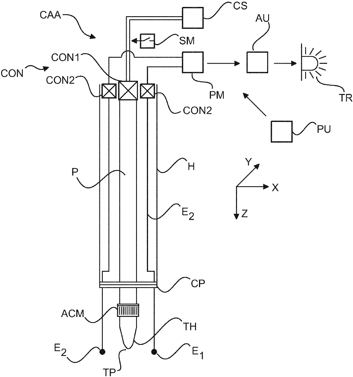
[0055] Turning now first to the disposal monitoring arrangement, this is in figure 1 As schematically shown in , the treatment monitoring arrangement is at least partially integrated into the cryoablation probe CAA. The probe CAA is arranged to administer cryoablation at a lesion in human or animal tissue.

[0056] For more details refer to figure 1 , shows an elongated, generally cylindrical probe body P (shown in partial cutaway side view) terminating at one end in a metal handling head TH. At the other end of the elongated probe body P there is a connector module CON.

[0057] The connector module CON comprises a first connector CON1 arranged to connect the probe to the cryogenic source CS. The...


PUM


Abstract

A cryo-ablation systems with a probe body (P) having a treatment head (TH) with a tip portion (TP) for contacting tissue at a region of contact and configured for imparting a temperature change to thetissue at said region of contact. A plurality of electrodes (Ej) are arranged spaced apart from said tip portion and around said tip portion, configured to measure an electrical property of the tissue in a neighborhood around said region of contact. Adhesion management means are also envisaged.

Description

technical field [0001] The invention relates to a device for supporting temperature changing operations in tissue, a method for supporting temperature changing operations in tissue, a computer program element and a computer readable medium. Background technique [0002] Cervical cancer is the most common cause of cancer death among women in relatively low resource settings such as refugee camps or countries with relatively low GDP per capita. [0003] At this point, downstaging efforts (i.e. cancer reduction measures) are seen in many developing countries (e.g. India, China) and are expected to be driven by large-scale screening by national health ministries or UN health agencies. It is planned to increase in the future. In particular, level 1 evidence (i.e., evidence from at least one appropriately designed randomized controlled trial) showed a benefit of relatively simple point-to-point management ("see and treat" strategy) to achieve downstaging and thus reduce risk of c...

Claims


Application Information

Patent Timeline
IPC IPC(8): A61B18/02
CPCA61B18/02A61B2018/00041A61B2018/00702A61B2018/00744A61B2018/00791A61B2018/00875A61B2018/00898
Inventor B·查克拉巴蒂S·塞特P·瓦集内帕里P·凯瑟沃浦K·苏巴拉曼
Owner KONINKLJIJKE PHILIPS NV
Why Eureka
Try Eureka