Cloth barrel clamping device

A technology of clamping device and cloth tube, which is applied in the direction of packaging, transportation and packaging, and external frames, etc., can solve the problem of damage to the cloth, and achieve the effects of not easy to damage the cloth, small size, and avoiding falling

Active Publication Date: 2018-02-16
宁波隆锐机械制造有限公司
View PDF6 Cites 5 Cited by
  • Summary
  • Abstract
  • Description
  • Claims
  • Application Information

AI Technical Summary

Problems solved by technology

[0005] The object of the present invention is to provide a cloth tube clamping device to solve the problem that the existing cloth tube clamping device damages the cloth

Method used


Image

  • Cloth barrel clamping device
  • Cloth barrel clamping device
  • Cloth barrel clamping device

Examples


Embodiment Construction

[0036] The present invention will be described in further detail below by means of specific embodiments:

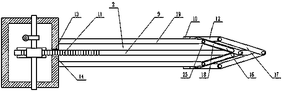
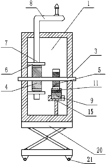
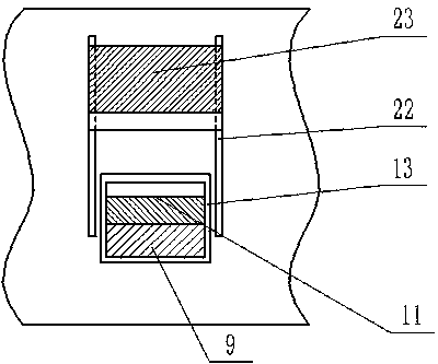
[0037] The reference signs in the drawings of the description include: box body 1, pressing mechanism 2, rotating shaft 3, worm wheel 4, gear 5, worm base 6, worm 7, rotating rod 8, push rod 9, telescopic end 10, rack 11. Pressure rod 12, sliding hole 13, gap 14, push rod slide seat 15, first connecting rod 16, second connecting rod 17, chute 18, positioning rod 19, lifting platform 20, roller 21, slide rail 22, Lock slide block 23, cloth tube 24, rotating shaft 25.

[0038] Such as figure 1The cloth tube clamping device shown includes a box body 1 with an inner cavity structure and a pressing mechanism 2. The box body 1 is provided with a sliding hole 13, and the pressing mechanism 2 includes two positioning rods parallel to each other. 19. The two positioning rods 19 have the same length, and one end of the positioning rod 19 is fixedly connected to the box body 1. Th...


PUM


Abstract

The invention relates to the field of spinning equipment and discloses a cloth barrel clamping device. The cloth barrel clamping device comprises a box body of an inner cavity structure and a compressing mechanism. A slide hole is formed in the box body; the compressing mechanism comprises two positioning bars which are parallel to each other, the two positioning bars are same in length, and one ends of the positioning bars are fixedly connected to the box body; the compressing mechanism also comprises a push rod, the push rod is located between the two positioning bars, the push rod is longerthan the positioning bars, one end of the push rod is slidably connected to the box body through the slide hole, and two connecting rods are arranged at one end, far from the box body, of the push rod. The invention aims to provide the cloth barrel clamping device to solve the problem that an existing cloth barrel clamping device damages cloth.

Description

technical field [0001] The invention relates to the technical field of textile equipment. Background technique [0002] After the fabric is processed, it is wound on the reel shaft, and the reel needs to be transported. The common way of transport is to manually transport the fabric tube, which is time-consuming and labor-intensive. [0003] The Chinese invention patent No. CN104891180A is an invention patent named "a kind of fabric tube lifting frame", which includes a lifting support frame, and a transverse beam is fixed on the two side support columns of the lifting support frame, and the middle part of the transverse beam has a The groove, the adjusting screw is in the groove, the two ends of the adjusting screw are hinged on the front side wall and the rear side wall of the groove, the rear part of the transverse beam has a driving motor groove, and the driving motor is fixed on the front side of the driving motor groove On the wall, the output shaft of the driving mot...

Claims


Application Information

Patent Timeline
Patent Type & Authority Applications(China)
IPC IPC(8): B65D61/00B65D67/02
CPCB65D61/00B65D67/02
Inventor 王健
Owner 宁波隆锐机械制造有限公司
Why Eureka
Try Eureka