Pool cleaner

A technology for cleaners and pools, applied in swimming pools, public buildings, gymnasiums, etc., can solve problems such as huge workload, inability to clean pool walls, and poor user experience

Pending Publication Date: 2018-02-16
INTEX IND (XIAMEN) CO LTD
View PDF19 Cites 4 Cited by
  • Summary
  • Abstract
  • Description
  • Claims
  • Application Information

AI Technical Summary

Problems solved by technology

[0002] Regardless of whether it is an outdoor pool or an indoor pool, dirt will always settle on the walls and bottom of the pool, which requires daily cleaning and maintenance. If manual cleaning is used, the workload will be huge; The pool cleaner is used to clean the pool; but the existing pool cleaner generally can only move at the bottom of the pool, so it can only clean the bottom of the pool, but not the wall of the pool. Manual cleaning is required, and the user experience is not very good

Method used


Image

  • Pool cleaner
  • Pool cleaner
  • Pool cleaner

Examples


Embodiment 1

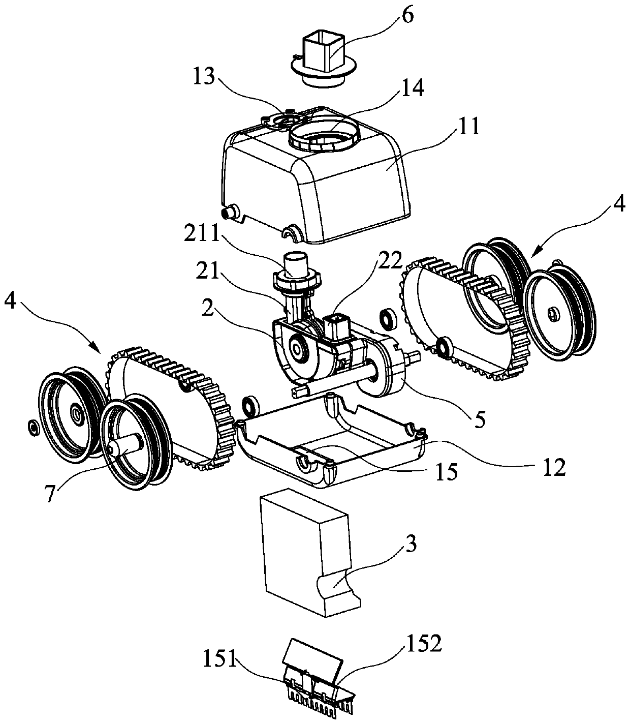
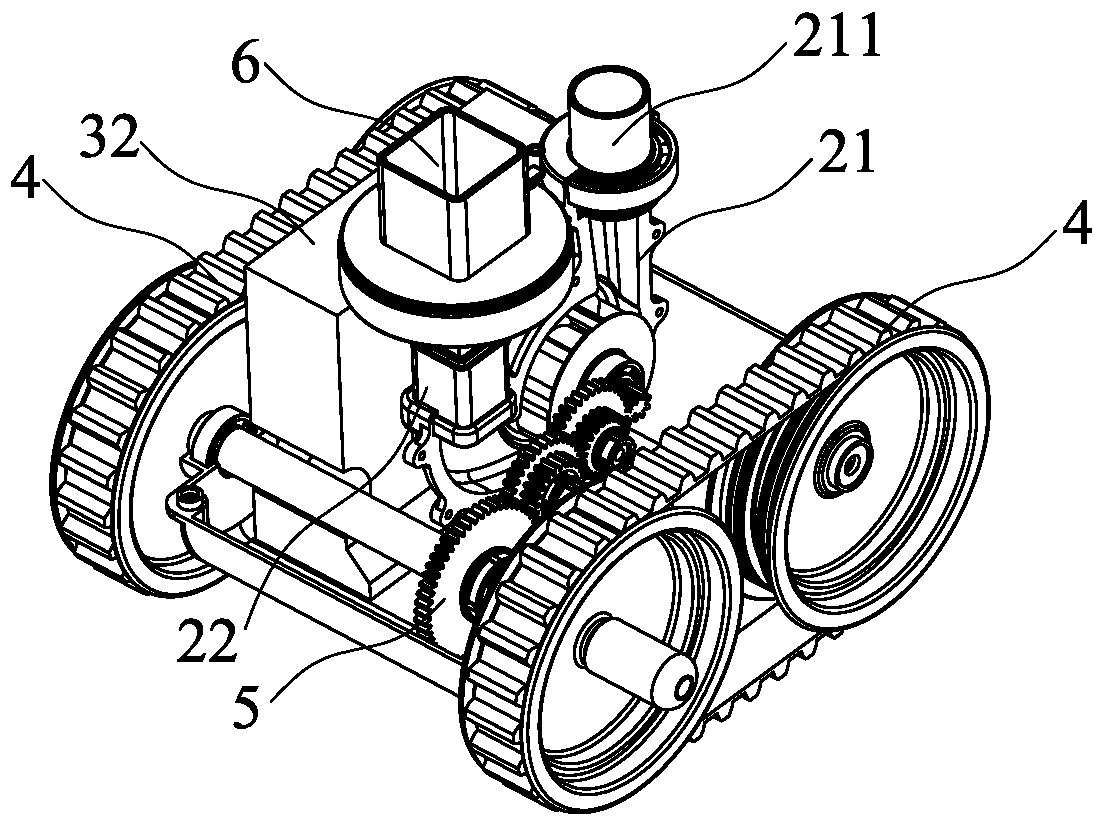
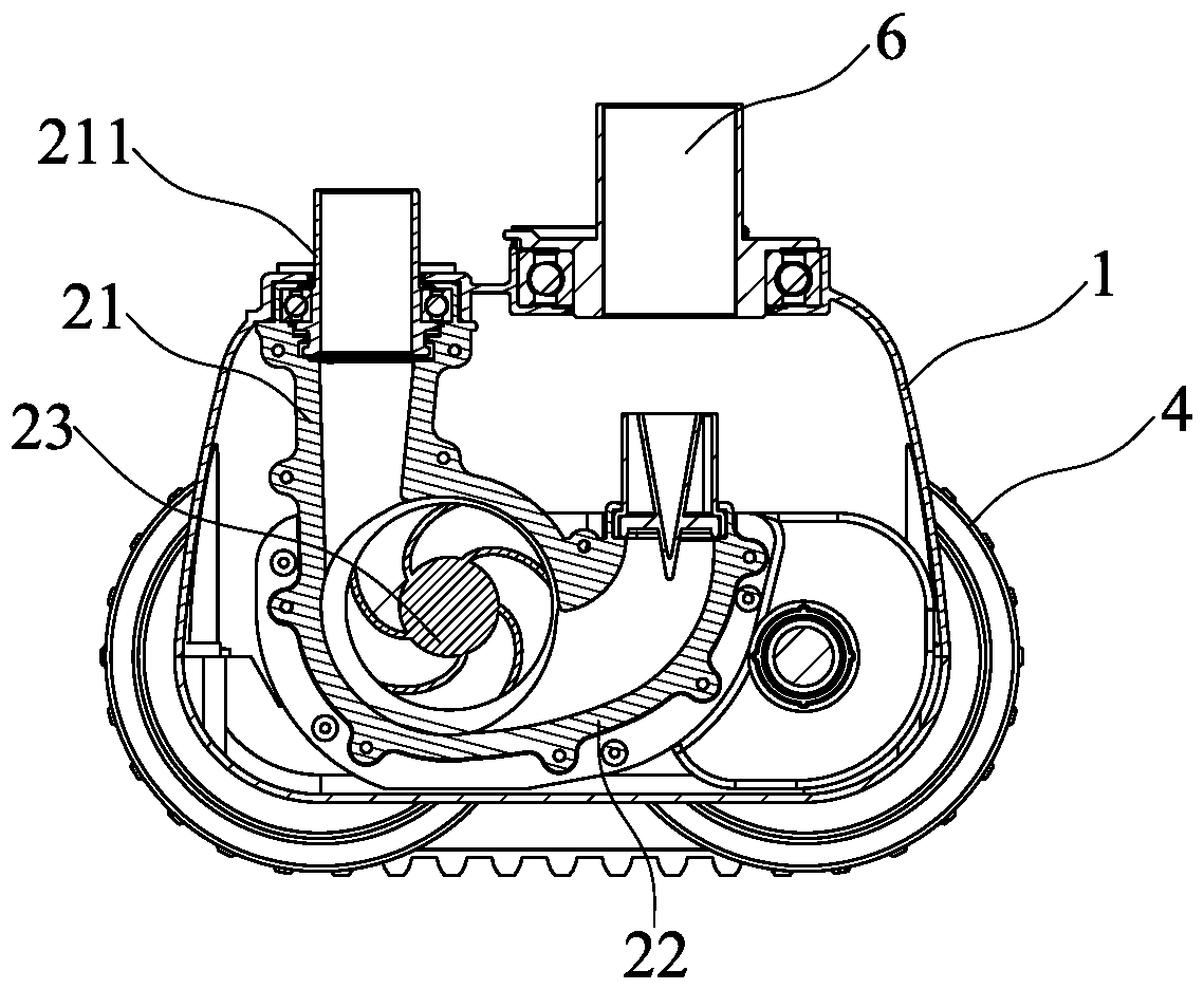
[0039] Such as Figure 1 to Figure 9 As shown, the pool cleaner of the present invention includes a housing 1, a hydraulic drive device 2, and a filter screen 3, which are used in conjunction with a water pump A,

[0040] Specifically, cooperate figure 1 and figure 2 As shown, the housing 1 includes a shell 11 and a bottom shell 12 , and the shell 11 and the bottom shell 12 are detachably matched by screws or buckles to form the shell 1 . The left and right sides of the housing 1 are provided with walking wheels 4, and the bottom of the housing 1 is provided with a sewage suction port 15; the filter screen 3 is arranged in the housing and covers the sewage suction port 15; There are perforations 13 and through holes 14; the through holes 14 are matched with spouts 6, and the injection direction of the spouts 6 is along the vertical upward direction of the housing 1; the perforations 13 are matched with connectors 211; in order to make the housing 1 It has strong grip when ...

Embodiment 2

[0046] In Embodiment 2, it is a further improvement of Embodiment 1. The difference between Embodiment 2 and Embodiment 1 lies in the spraying direction of the nozzle 6 and the matching relationship between the nozzle 6 and the through hole 14 on the housing 1 .

[0047] Cooperate Figure 10 to Figure 18 As shown, in the second embodiment, the nozzle 6 is rotatably fitted on the through hole 14 of the housing 1 through a bearing 61, and the injection direction of the nozzle 6 is along the oblique upward direction of the housing 1; wherein the The spraying direction of the spout 6 may form an angle greater than zero and less than or equal to forty-five degrees with the vertical upward direction of the housing 1; a limiting device for limiting the rotation angle of the spout 6 is provided between the spout 6 and the through hole 14, The limiting device includes a rotation clamping point 62 on the other side of the nozzle 6 opposite to one side of the injection direction of the n...


PUM


Abstract

The invention discloses a pool cleaner which is used by cooperating with a water pump. The pool cleaner comprises a shell, a hydraulic driving device and a filter screen; traveling wheels are arrangedon the left side and the right side of the shell, and a pollution suction opening is formed in the bottom of the shell; the filter screen is arranged inside the shell, and the pollution suction opening is covered with the filter screen; a penetrating hole and a through hole are formed in the top of the shell, and the through hole is matched with a nozzle; the spraying direction of the nozzle is the vertical upward direction or the oblique upward direction of the shell; the penetrating hole is matched with a connector, and the hydraulic driving device is arranged inside the shell and comprisesa water inlet pipe connected with the connector, a water outlet pipe communicating with the nozzle and an impeller between the water inlet pipe and the water outlet pipe; and the impeller is in linkage with the travelling wheels through transmission mechanisms. The pool cleaner can move at the pool bottom and on the pool wall of a pool, the pool bottom and the pool wall of the pool are cleaned accordingly, and the cleaning effect of the pool is ensured.

Description

technical field [0001] The present invention relates to the field of pool cleaning, in particular to pool cleaners. Background technique [0002] Regardless of whether it is an outdoor pool or an indoor pool, dirt will always settle on the walls and bottom of the pool, which requires daily cleaning and maintenance. If manual cleaning is used, the workload will be huge; The pool cleaner is used to clean the pool; but the existing pool cleaner generally can only move at the bottom of the pool, so it can only clean the bottom of the pool, but not the wall of the pool. Manual cleaning is required, and the user experience is not very good. Contents of the invention [0003] The object of the present invention is to provide a pool cleaner, which is used in conjunction with a water pump and can move on the bottom and wall of the pool to clean the bottom and wall of the pool. [0004] In order to achieve the above object, the solution of the present invention is: [0005] A poo...

Claims


Application Information

Patent Timeline
IPC IPC(8): E04H4/16
CPCE04H4/1663
Inventor 黄志雄张文孝许耀元
Owner INTEX IND (XIAMEN) CO LTD
Why Eureka
Try Eureka