Eureka AIR delivers breakthrough ideas for toughest innovation challenges, trusted by R&D personnel around the world.

Calculation method of line frequency for tdi camera's vertical orbit rotation and sweep imaging

A calculation method and vertical orbit technology, which are applied in the field of horizontal frequency calculation of vertical orbit rotation and sweep imaging of TDI cameras, can solve problems such as difficulty in horizontal frequency calculation, and achieve the effect of expanding calculation methods, simple and reliable methods, and expanding application fields.

Active Publication Date: 2019-11-29
CHANGCHUN INST OF OPTICS FINE MECHANICS & PHYSICS CHINESE ACAD OF SCI
View PDF7 Cites 0 Cited by
  • Summary
  • Abstract
  • Description
  • Claims
  • Application Information

AI Technical Summary

Problems solved by technology

[0004] In order to solve the difficult problem of difficult calculation of line frequency caused by dynamic changes of multiple velocity vectors during satellite rapid rotation and ultra-large width push-broom imaging, the present invention provides a line frequency calculation method for TDI camera vertical orbit rotation swing-sweep imaging

Method used


Image

  • Calculation method of line frequency for tdi camera's vertical orbit rotation and sweep imaging
  • Calculation method of line frequency for tdi camera's vertical orbit rotation and sweep imaging
  • Calculation method of line frequency for tdi camera's vertical orbit rotation and sweep imaging

Examples


specific Embodiment approach 1

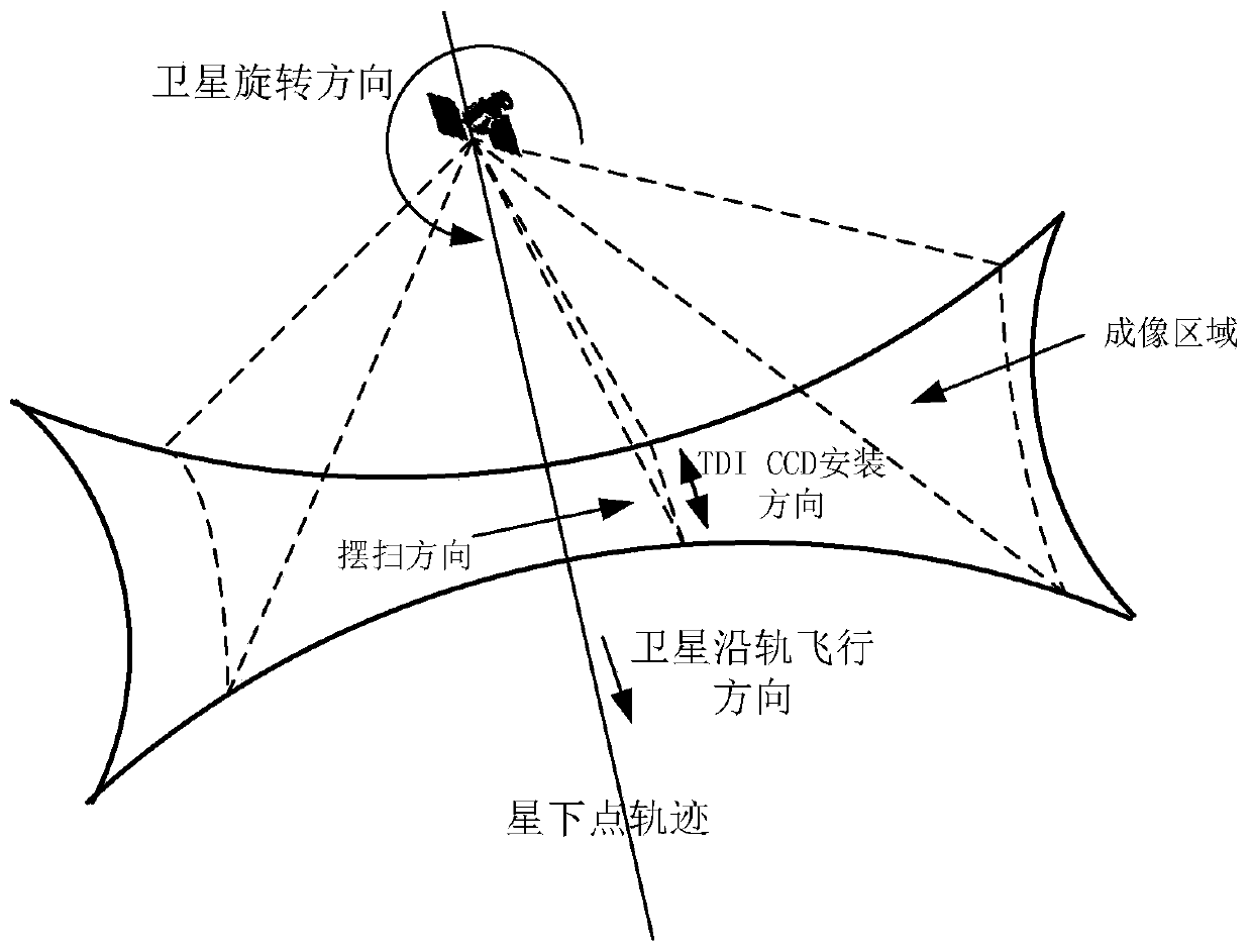
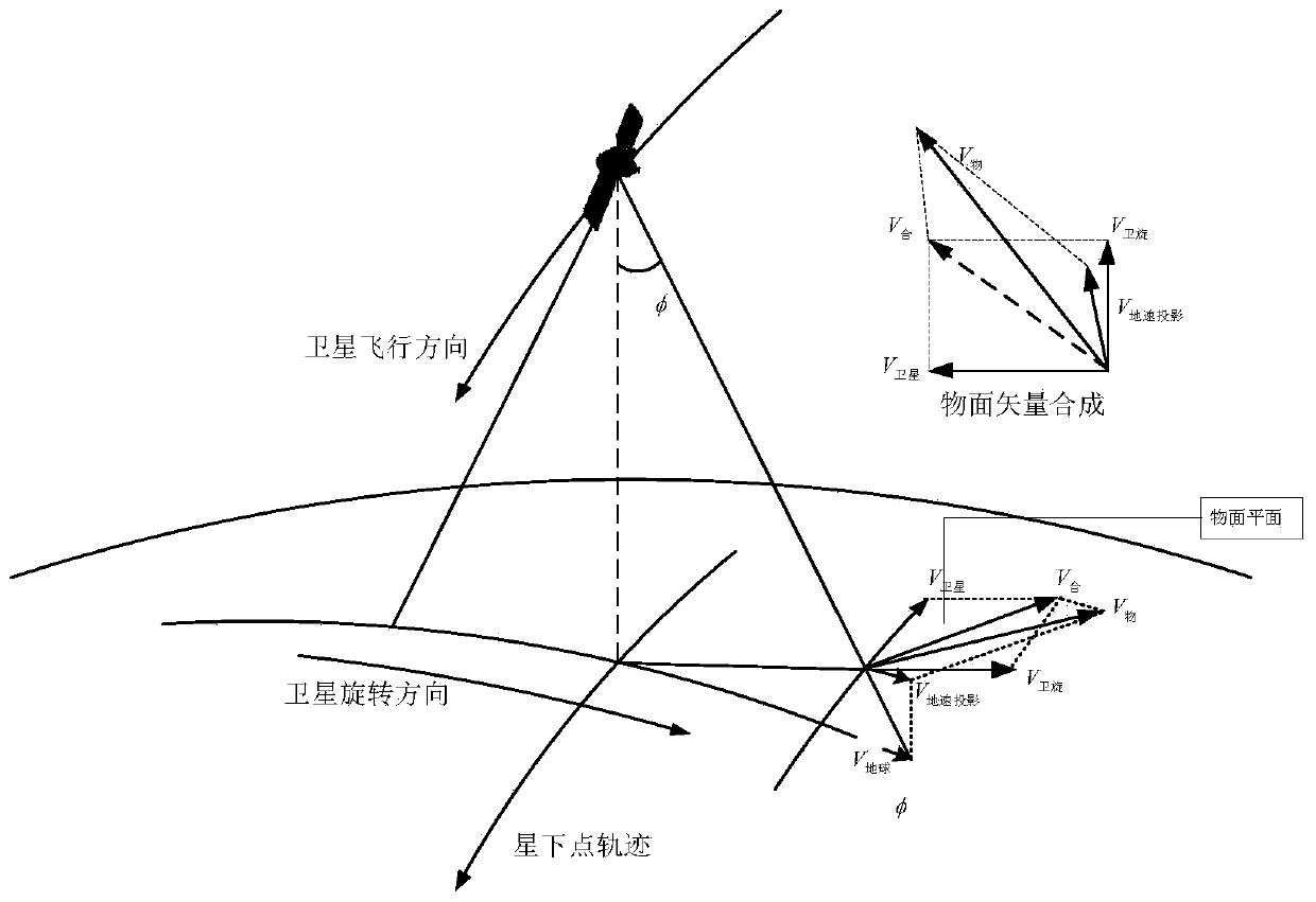
[0033] Specific implementation mode 1. Combination Figure 1 to Figure 4 Description of this embodiment, the line frequency calculation method of TDI camera vertical orbit rotation swing imaging. The line frequency is determined by the combined speed of the target scene on the image plane and the size of the CCD pixel. , there are three velocity vectors: the earth's rotation velocity, the satellite's precession velocity and the satellite's rotational angular velocity. Because the three velocity vectors are not on the same plane;

[0034] Firstly, each velocity vector should be calculated separately and projected onto the object surface for synthesis.

[0035] V 地 = ω 地 × R 地 ;

[0036]

[0037] V 卫旋 = ω 卫 × L 侧 ;

[0038]

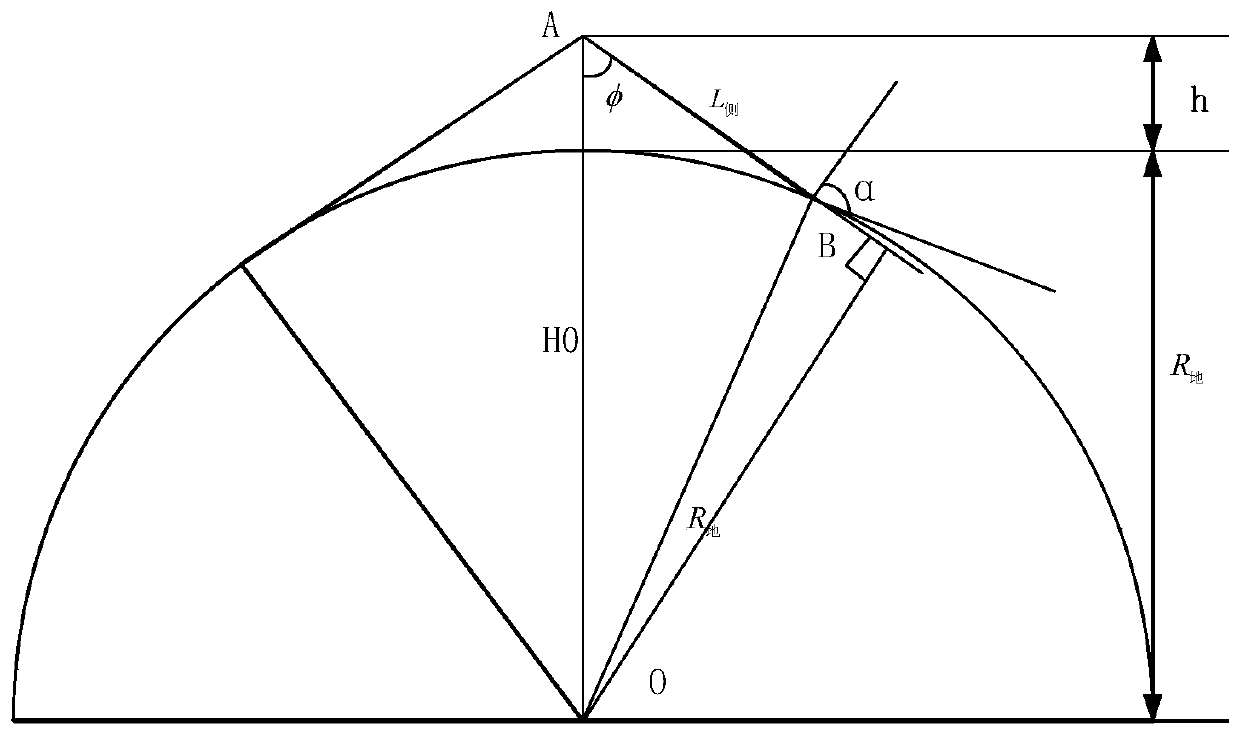
[0039] Among them, ω 地 =7.2921×10 -5 rad / s; R 地 =6371.004km; ω 卫 =10° / s; μ=3.986×10 14 ;H 0 =h+R 地 ;φ is the angular position corresponding to the rotation;

[0040] V 地速投影 =V 地 ×cosφ

[0041] Then the satellite speed and the camer...

specific Embodiment approach 2

[0053] Specific Embodiment 2. This embodiment is an embodiment of the method for calculating the line frequency of a TDI camera vertical orbit rotation and sweep imaging described in Embodiment 1: calculate the detector according to the orbital height, geographic latitude and sweep angle position The vertical rail swings to sweep the line frequency.

[0054] (1) Assuming that the satellite orbit height is h=500km, the earth’s radius R=6371km, and the latitude is 0°, when the vertical orbit sweep image reaches a sideways swing of 45°, there are three velocity vectors as follows: Figure 4 As shown, they are:

[0055] Earth's rotation speed V 地 = ω 地 × R 地 =464.58m / s

[0056]satellite precession speed

[0057] Satellite rotation sweep speed V 旋 = ω 卫 × L 侧 =123385.68m / s

[0058] (2) Calculation of combined velocity vector on object surface

[0059] i 0 =97.4°

[0060] α=atan(V 旋 / V 卫星 )+i 0

[0061]

[0062] (3) Calculation of the uplink frequency on the ima...


PUM


Abstract

The line frequency calculation method of TDI camera vertical orbit rotation swing scan imaging involves the field of photoelectric imaging technology. In order to solve the problem of difficult calculation of line frequency caused by dynamic changes of multiple velocity vectors during satellite fast rotation and ultra-large width push-broom imaging, this method aims at the traditional The calculation of line frequency for static push-broom imaging of remote sensing satellites cannot meet the needs of rapid and real-time changes in the line frequency of dynamic imaging of satellite rotation and sweep. Earth rotation speed, satellite precession speed and satellite rotation speed, project the three velocity vectors onto the object plane for synthesis, calculate the combined velocity vector on the image plane, use the ratio of the pixel size to the combined velocity vector on the image plane to calculate the dynamic The real-time line frequency of swing scan imaging is used to achieve the purpose of real-time line frequency registration of vertical track swing scan dynamic imaging. The method of the invention is simple, reliable and easy to implement, and expands the application field of dynamic swing-sweep satellites.

Description

technical field [0001] The invention relates to the technical field of photoelectric imaging, in particular to a method for calculating line frequency of TDI camera vertical orbit rotary swing scanning imaging. Background technique [0002] At present, in order to achieve push-broom imaging in a wider range, optical remote sensing satellites have developed from the orbital sub-satellite point or large side-swing push-broom imaging mode to the vertical-orbit rotary swing-broom imaging mode. CCD splicing or simultaneously increasing the camera’s side swing capability to achieve push-broom imaging in a certain field of view in a large area, which cannot achieve ultra-large and wide-range imaging, and vertical orbit rotation swing imaging uses the satellite’s rapid rotation to make it parallel to the satellite’s flight direction The linear array CCD detector rotates continuously at 360° to realize fast push-broom imaging in the vertical orbit direction, thereby maximizing the sa...

Claims


Application Information

Patent Timeline
Patent Type & Authority Patents(China)
IPC IPC(8): G01C11/02
CPCG01C11/025
Inventor 杨秀彬王家骐金光王旻常琳
Owner CHANGCHUN INST OF OPTICS FINE MECHANICS & PHYSICS CHINESE ACAD OF SCI
Why Eureka
Eureka Blog
Learn More