A pressure testing device for a sheath

A sheathing and pressure testing technology, applied in measuring devices, using stable tension/pressure testing material strength, instruments, etc., to achieve the effect of improving pressure testing efficiency and reducing residence time

Inactive Publication Date: 2018-02-16
XIANGYANG WU ER WU PUMP IND
View PDF6 Cites 1 Cited by
  • Summary
  • Abstract
  • Description
  • Claims
  • Application Information

AI Technical Summary

Problems solved by technology

[0003] The purpose of the present invention is to provide a pressure test device for the sheath in order to solve the disadvantage of the

Method used


Image

  • A pressure testing device for a sheath

Examples


Embodiment

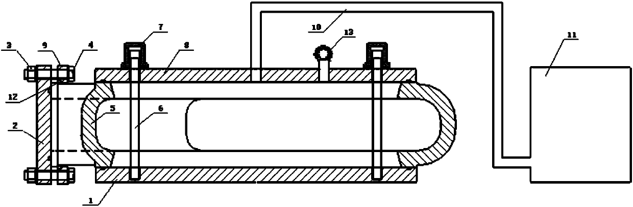
[0021] A kind of sheath pressure testing device of the present invention, as figure 1 As shown, it includes a bottom plate 1, a side plate 2, an upper plate 8, a half inner ring 12, a side plate clamp ring 9, a booster pump 11, and a booster pipe 10;

[0022] The upper surface of the bottom plate 1 is a clamping plane, the upper surface of the bottom plate 1 is provided with a sealing ring installation groove whose slotting position matches the shape of the lower port of the sheath 5, and the middle part of the upper surface of the bottom plate 1 is provided with a threaded blind hole;

[0023] The lower surface of the upper plate 8 is a clamping plane, and the lower surface of the upper plate 8 is provided with a sealing ring installation groove whose slotting position matches the shape of the upper port of the sheath 5, and the middle part of the upper plate 8 is provided with a screw through hole for water injection. hole and pressure gauge mounting hole;

[0024] The righ...


PUM


Abstract

The invention relates to a pressure testing device for a sheath, and belongs to the field of fluid machinery. The device includes a bottom plate, a side plate, a top plate, a split-half inner ring, aside-plate clamping ring, a booster pump and a pressure boosting pipe. The top plate and the bottom plate are disposed at upper and lower end ports of the sheath. The top and bottom plates are clampedtightly and sealed through studs. The side plate is mounted outside a lateral outlet of the sheath. The rear end of a port connection stage of the lateral outlet of the sheath is sleeved with the split-half inner ring and the side-plate clamping ring. The side-plate clamping ring and the side plate are fastened through screws and nuts. The device achieves tests on actual pressure of a separated sheath component, and can effectively control blank quality of the sheath. Complete machine assembling before pressure testing is not needed, thus increasing the pressure testing efficiency and reducing component retention time.

Description

technical field [0001] The invention relates to a sheath pressure testing device, which belongs to the field of fluid machinery. Background technique [0002] The pressure test of the main flow parts of the heavy-duty slurry pump is an important process to check the quality of the casting, the defect of the blank, and the pressure of the casting. If the traditional process needs to carry out the pressure test, the sheath, the front guard plate, the rear guard plate, the front pump casing and the rear pump casing must be assembled before proceeding. For the sheath connected to all parts in the heavy-duty slurry pump, if the pressure test fails, all parts need to be removed and the sheath replaced to increase the test work intensity; and because each part is processed in batches, the processed sheath needs to be The pressure test can only be done after all other parts are processed, and the waiting time for the pressure test is prolonged, so that a large number of parts are s...

Claims


Application Information

Patent Timeline
IPC IPC(8): G01N3/12
CPCG01N3/12G01N2203/0019G01N2203/0048
Inventor 赵鹏尹禹史浩汪娇
Owner XIANGYANG WU ER WU PUMP IND
Why Eureka
Try Eureka