CTS array antenna system with wide angle scanning function

An array antenna and wide-angle scanning technology, which is applied to specific array feeding systems, antennas, antenna arrays, etc., can solve problems such as difficulty in meeting broadband requirements, narrowing of the working frequency band of array elements, and increased network loss. Achieve the effects of small feed loss, low profile and high gain

Active Publication Date: 2018-02-16
XIAN INSTITUE OF SPACE RADIO TECH
View PDF10 Cites 2 Cited by
  • Summary
  • Abstract
  • Description
  • Claims
  • Application Information

AI Technical Summary

Problems solved by technology

For one-dimensional scanning waveguide slot antennas, as the gain of the array element increases, the working frequency band of the array element will become narrower, and it is difficult to meet the broadband requirements; for one-dimensional scanning microstrip line elements and oscillator line elements, it is necessary For the power combining network, as the gain of the array element increases, the network loss will increase, and accordingly, the heat consumption will also be greater

Method used


Image

  • CTS array antenna system with wide angle scanning function
  • CTS array antenna system with wide angle scanning function
  • CTS array antenna system with wide angle scanning function

Examples


Embodiment Construction

[0053] In order to make the purpose, technical solution and advantages of the present invention clearer, the following will further describe the public implementation manners of the present invention in detail with reference to the accompanying drawings.

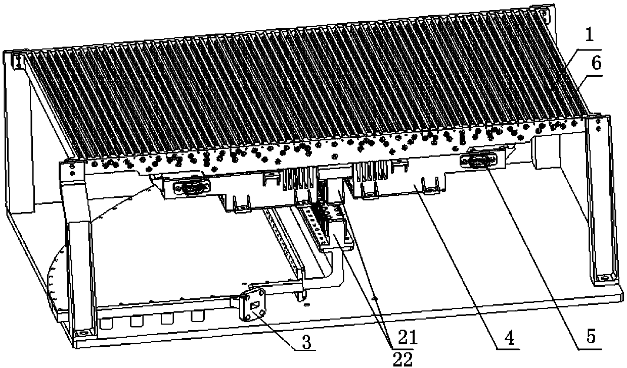
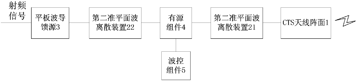
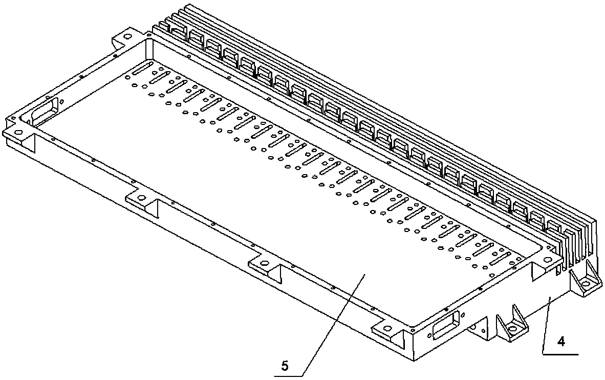
[0054] refer to figure 1 , shows a schematic structural diagram of a CTS array antenna system with a wide-angle scanning function in an embodiment of the present invention. refer to figure 2 , shows a structural block diagram of a CTS array antenna system with a wide-angle scanning function in an embodiment of the present invention. In this embodiment, the structure of the CTS (Continuous Transverse Stub, CTS, continuous transverse stub) array antenna system with wide-angle scanning function includes: a CTS antenna array 1, a pair of alignment plane wave dispersion devices, and a flat waveguide feeder. Source 3, active component 4 and wave steering component 5. Wherein, the pair of quasi-plane wave discrete devices inclu...


PUM


Abstract

The invention discloses a CTS array antenna system with a wide angle scanning function. A pair of quasi-planar wave discrete apparatuses are connected between a CTS antenna array surface and a slab waveguide feed source, so that discretization of the incident quasi-planar waves is realized, and a coaxial mode is converted, so that a conventional power division network is omitted; and by virtue ofan active assembly arranged between the pair of the quasi-planar wave discrete apparatuses, phase-control scanning of a wave beam is realized, thereby realizing relatively low feed loss and relativelylow heat consumption. Therefore, the CTS array antenna system with the wide angle scanning function disclosed in the invention has the characteristics of broadband, high gain and wide angle scanningand the advantages of low profile, low cost and low heat consumption.

Description

technical field [0001] The invention belongs to the technical field of antennas, in particular to a CTS array antenna system with a wide-angle scanning function. Background technique [0002] At present, the commonly used mechanically movable reflector antenna has a large envelope size; while the traditional one-dimensional scanning phased array antenna mostly uses waveguide slot line elements, microstrip line elements, and oscillator line elements. For one-dimensional scanning waveguide slot antennas, as the gain of the array element increases, the working frequency band of the array element will become narrower, and it is difficult to meet the broadband requirements; for one-dimensional scanning microstrip line elements and oscillator line elements, it is necessary In the power combining network, as the gain of the array element increases, the network loss will increase, and accordingly, the heat consumption will also be greater. Contents of the invention [0003] The t...

Claims


Application Information

Patent Timeline
Patent Type & Authority Applications(China)
IPC IPC(8): H01Q23/00H01Q21/00H01Q3/36H01Q1/50
CPCH01Q1/50H01Q3/36H01Q21/0006H01Q23/00
Inventor 贾秀娟何佳欢张明涛薛江波史明徐进王虎辛丽马俊杨昭宁
Owner XIAN INSTITUE OF SPACE RADIO TECH
Why Eureka
Try Eureka