Anti-thunder lightning-protection device used for pipeline joints

A lightning protection device and pipeline joint technology, applied in the direction of corona discharge device, electrical components, circuits, etc., can solve the problems of uneven distribution, easy breakdown of thundercloud and lightning rod air, lightning current discharge of lightning energy, etc. The effect of changing the lightning protection method, reducing the probability of being struck by lightning, and promoting the formation of a uniform circuit

Inactive Publication Date: 2018-02-16
江苏镇德电力设备有限公司
View PDF4 Cites 1 Cited by
  • Summary
  • Abstract
  • Description
  • Claims
  • Application Information

AI Technical Summary

Problems solved by technology

[0002] The traditional lightning rod is installed at the highest point of the lightning protection object. When lightning occurs, this highest point and the thundercloud form an extremely unevenly distributed electric field environment, which makes the air between the thundercloud and the lightning rod easy to be broken down, and the lightning current is extremely high. It is easy to discharge the lightning energy to the earth through the lightning rod. This lightning protection method that discharges the lightning energy through the lightning rod itself is more likely to cause a direct lightning strike. Therefore, the traditional lightning rod leads the lightning to itself and the ground discharges the lightning energy. Lightning protection for valves, pipeline connectors, signal lines and signal connectors provides safety protection

Method used


Image

  • Anti-thunder lightning-protection device used for pipeline joints

Examples


Embodiment Construction

[0015] The present invention will be further described below in conjunction with the accompanying drawings. The following examples are only used to illustrate the technical solution of the present invention more clearly, but not to limit the protection scope of the present invention.

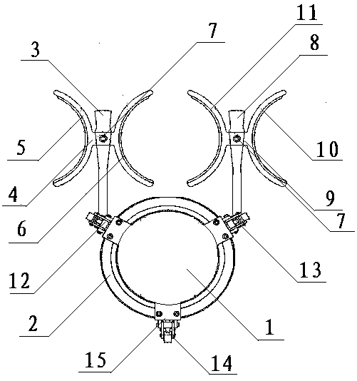
[0016] figure 1 It is a structural representation of the present invention. The invention proposes a lightning protection device for pipeline joints, which is characterized in that it includes a pipeline 1, and a matching cylindrical sleeve 2 is set on the outer circumference of the pipeline 1, and three equidistant symmetrical Distributed hinge blocks 15, the two hinge blocks 15 on the upper part are respectively fixed with the first vertical rod 3 and the second vertical rod 8 which are symmetrically distributed on the left and right, and the first vertical rod 3 is fixedly arranged There is a first lightning protection ring 4, and a second lightning protection ring 9 is fixedly arranged on ...


PUM


Abstract

The invention discloses an anti-thunder lightning-protection device used for pipeline joints. The anti-thunder lightning-protection device comprises pipelines, wherein matched cylindrical sleeves sleeve the peripheries of the pipelines; three equally spaced and symmetrically distributed hinged blocks are embedded into each cylindrical sleeve; a first vertical rod piece and a second vertical rod piece in symmetrical distribution are fixedly arranged on the two hinged blocks positioned at the upper part respectively; a first lightning-protection ring is fixedly arranged on each first vertical rod piece; a second lightning-protection ring is fixedly arranged on each second vertical rod piece; and the first lightning-protection rings and the second lightning-protection rings are symmetricallyarranged. The device is applied to the technical field of anti-thunder lightning-protection design of pipeline connecting pieces or circuit connecting pieces, uniformly distributed inductive charge layers are formed around the first lightning-protection rings and the second lightning-protection rings, and an electric field environment with relatively uniform distribution is formed by the inductivecharge layers and thundercloud, so that the probability that pipelines or signal circuits suffer from lightning strokes is obviously reduced.

Description

technical field [0001] The invention relates to a lightning protection device for pipeline joints, belonging to the technical field of pipeline lightning protection design. Background technique [0002] The traditional lightning rod is installed at the highest point of the lightning protection object. When lightning occurs, this highest point and the thundercloud form an extremely unevenly distributed electric field environment, which makes the air between the thundercloud and the lightning rod easy to be broken down, and the lightning current is extremely high. It is easy to discharge the lightning energy to the earth through the lightning rod. This lightning protection method that discharges the lightning energy through the lightning rod itself is more likely to cause a direct lightning strike. Therefore, the traditional lightning rod leads the lightning to itself and the ground discharges the lightning energy. The lightning protection of valves, pipeline connectors, signa...

Claims


Application Information

Patent Timeline
Patent Type & Authority Applications(China)
IPC IPC(8): H01T19/02
CPCH01T19/02
Inventor 赵星川
Owner 江苏镇德电力设备有限公司
Why Eureka
Try Eureka