Ink recovery device for printing press

A recycling device and printing machine technology, applied in the direction of printing machines, printing, general parts of printing machinery, etc., can solve the problems of complex operation, time-consuming and labor-intensive cleaning, not completely clean, etc., and achieve huge economic benefits, broad market prospects, and design Creatively conceived effects

Inactive Publication Date: 2018-02-23
张斐斐
View PDF6 Cites 4 Cited by
  • Summary
  • Abstract
  • Description
  • Claims
  • Application Information

AI Technical Summary

Problems solved by technology

[0002] Ink is an important material for printing. It expresses patterns and characters on the substrate by printing or inkjet painting. The ink includes main components and auxiliary components. They are evenly mixed and rolled repeatedly to form a viscous colloidal fluid. , in the field of packaging printing, due to the excessive speed of the printing roller in the printing process of the existing printing machine, a lot of ink will be thrown off by the printing roller, and when the printing machine works for a long time, there will be ink remaining on the ink roller, printing plate , or the surface of the blanket needs to be cleaned; if things go on like this, it will cause waste, increase the cost of wastewater treatment, and is not conducive to environmental protection. Therefore, the demand for a printing ink recovery device is increasing
[0003] Most of the ink recovery devices of printing machines currently on the market need to separately control the ink outlet device and the cleaning device, which is not only complicated to operate, but also time-consuming and laborious; the cleaning of some ink recovery devices of printing machines is not completely clean, and the recovery rate is not high. low, and it is easy to pollute and block equipment; there are also some printing gold ink recovery devices, the water source utilization rate is low, not only easy to waste water, but also pollute the environment, etc. Therefore, a printing ink recovery device is proposed to solve the above problems

Method used


Image

  • Ink recovery device for printing press
  • Ink recovery device for printing press
  • Ink recovery device for printing press

Examples


Embodiment Construction

[0022] The following will clearly and completely describe the technical solutions in the embodiments of the present invention with reference to the accompanying drawings in the embodiments of the present invention. Obviously, the described embodiments are only some, not all, embodiments of the present invention. Based on the embodiments of the present invention, all other embodiments obtained by persons of ordinary skill in the art without making creative efforts belong to the protection scope of the present invention.

[0023] see Figure 1-5 , the present invention provides a technical solution:

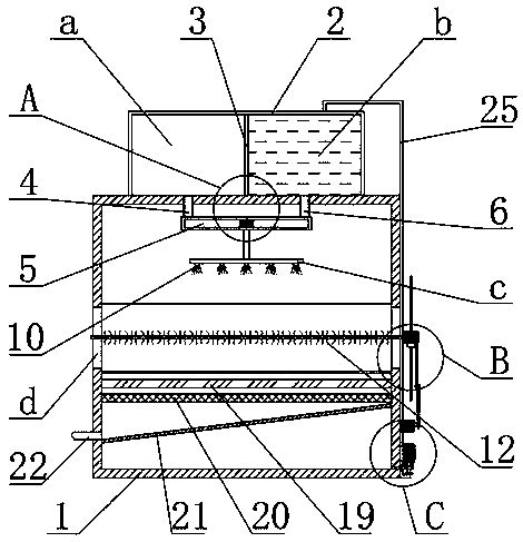
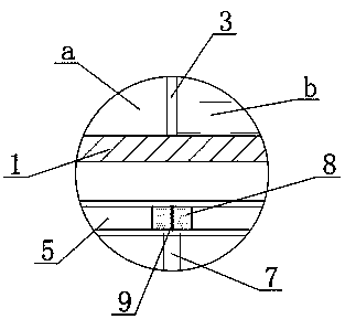
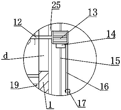
[0024] An ink recovery device for a printing machine, comprising a box body 1, a liquid storage tank 2 is provided on the top surface of the box body 1, and a partition 3 is fixedly connected to the inner side of the liquid storage tank 2, and the partition 3 stores The liquid tank 2 is divided into an ink tank a and a clean water tank b arranged on the left and right, the bottom ...


PUM


Abstract

The invention relates to the technical field of printing equipment, in particular to an ink recovery device for a printing press. The ink recovery device comprises a box, wherein a sloping plate is fixedly connected in the box, slide grooves are formed in the box, a brush is glidingly connected in the slide grooves, the right end of the brush is fixedly connected with a main motor, the bottom endof the main motor is fixedly connected with a slider which is glidingly connected with a slide bar, the right end surface of the slider is rotationally connected with a first connecting rod, the otherend of the first connecting rod is rotationally connected with a second connecting rod, the other end of the second connecting rod is fixedly connected with an auxiliary motor, and the other end of the auxiliary motor is fixedly connected with the box. By means of arrangement of the sloping plate, the brush, the main motor, the slide bar and the slider, ink on the sloping plate can be cleaned, cleanness in the box is kept, the cleaned ink can be recovered, and the ink recovery device has huge economic benefit and broad market prospect and is worth popularizing and using.

Description

technical field [0001] The invention relates to the technical field of printing equipment, in particular to an ink recovery device for a printing machine. Background technique [0002] Ink is an important material for printing. It expresses patterns and characters on the substrate by printing or inkjet painting. The ink includes main components and auxiliary components. They are evenly mixed and rolled repeatedly to form a viscous colloidal fluid. , in the field of packaging printing, due to the excessive speed of the printing roller in the printing process of the existing printing machine, a lot of ink will be thrown off by the printing roller, and when the printing machine works for a long time, there will be ink remaining on the ink roller, printing plate , or the surface of the blanket needs to be cleaned; if things go on like this, it will cause waste, increase the cost of wastewater treatment, and is not conducive to environmental protection. Therefore, the demand for ...

Claims


Application Information

Patent Timeline
Patent Type & Authority Applications(China)
IPC IPC(8): B41F31/20B41F35/00B01D36/00
CPCB41F31/20B01D36/00B41F35/00
Inventor 张斐斐
Owner 张斐斐
Why Eureka
Try Eureka