One-hand hand-tearing device for rolling bags

A continuous bag, hand tearing technology, applied in the directions of packaging, winding strips, transportation and packaging, etc., can solve the problem that there is no operating device for continuous bags, inconvenient operation, and it is difficult to coordinate with both hands to tear off the continuous bags. And other issues

Active Publication Date: 2019-08-09
扬州市鼎鑫食品集团有限公司
View PDF5 Cites 0 Cited by
  • Summary
  • Abstract
  • Description
  • Claims
  • Application Information

AI Technical Summary

Problems solved by technology

However, in the process of tearing off the roll bag along the separation line, two hands are required to cooperate. One hand needs to fix the roll bag wound on the reel, and the other hand needs to pull the roll bag to be torn off. It's inconvenient
Especially when you have items in your hands, it is difficult to coordinate your hands to tear off the rolling bag
[0003] In addition, there is currently no operating device on the market that can tear off the rolling bag with one hand

Method used


Image

  • One-hand hand-tearing device for rolling bags
  • One-hand hand-tearing device for rolling bags
  • One-hand hand-tearing device for rolling bags

Examples


Embodiment approach 1

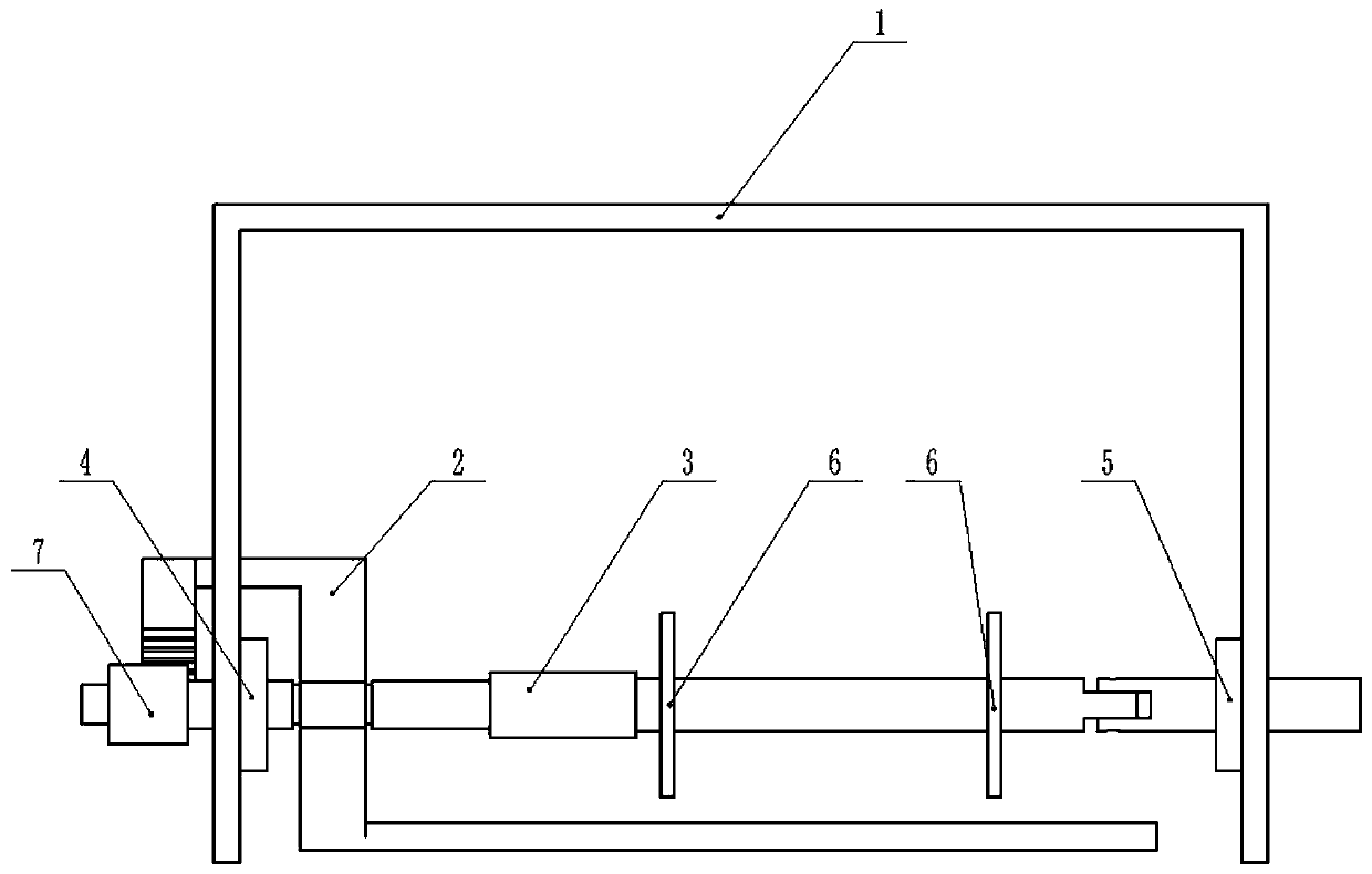
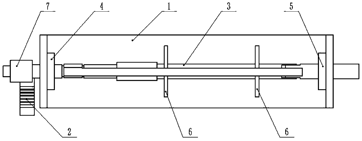
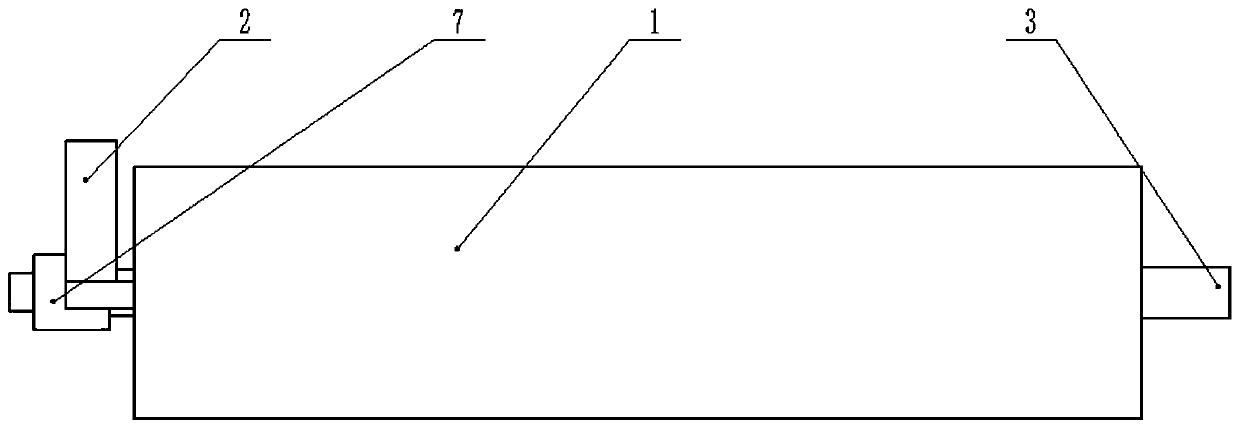
[0036] Combine below figure 1 , 2 , 3, 4, 5, 6, 7, 8, 9, 10, 11, 12, 13, and 14 illustrate this embodiment, a device for tearing bags with one hand with one hand in the present invention consists of a connecting plate 1, a blocking block 2, The connecting shaft 3, the bearing I4, the bearing II5, the pressing ring 6 and the gear 7 are composed, and the roll bag can be quickly torn off with one hand, and the roll bag can be quickly replaced.

[0037] One end of the connecting shaft 3 is rotatably connected to one end of the connecting plate 1 through the bearing I4, and the other end of the connecting shaft 3 is rotatably connected to the other end of the connecting plate 1 through the bearing II5, so that The connecting shaft 3 is rotatably connected to the connecting plate 1 , and the connecting shaft 3 can rotate around the axis of the connecting shaft 3 on the connecting plate 1 . There are two compression rings 6, both of which are fixedly connected to the connecting sha...

Embodiment approach 2

[0039] Combine below figure 1 , 2 , 3, 4, 5, 6, 7, 8, 9, 10, 11, 12, 13, and 14 describe this embodiment, and this embodiment is a further description of Embodiment 1.

[0040] The connection plate 1 is provided with a connection hole 1-1 for connecting the connection shaft 3 and a rotation slot 1-2 for facilitating the rotation of the locking block 2 . The connection hole 1-1 is used to connect the connection shaft 3, the diameter of the connection hole 1-1 is larger than the diameter of the connection shaft 3, and the connection hole 1-1 will not affect the rotation of the connection shaft 3. The rotation groove 1-2 is set large enough to not affect the rotation of the block 2.

Embodiment approach 3

[0042] Combine below figure 1 ,2 , 3, 4, 5, 6, 7, 8, 9, 10, 11, 12, 13, and 14 describe this embodiment, and this embodiment is a further description of Embodiment 1.

[0043] The catch 2 is composed of a connecting ring 2-1, a rectangular plate I2-2, a rectangular plate II2-3, a cylinder 2-4, a rectangular bar 2-5 and a stop bar 2-6. The connecting ring 2 -1 is provided with a groove 2-1-1 through the connecting ring 2-1, the groove 2-1-1 makes the connecting ring 2-1 have a certain elasticity, and the opening size of the groove 2-1-1 can be adjusted, Thus, the catch 2 is rotatably connected to the connecting shaft 3 . The blocking bar 2-6 is provided with locking teeth 2-6-1. The connecting ring 2-1 is fixedly connected with the rectangular plate I2-2 and the rectangular plate II2-3 by welding, and the rectangular plate I2-2 and the rectangular plate II2-3 are fixed on the axis of the connecting ring 2-1 Symmetrically distributed; the upper end of the rectangular plate I2...


PUM


Abstract

The invention belongs to the field of daily apparatuses and particularly relates to a single-hand manual tearing device for a rolling bag. The single-hand manual tearing device is composed of a connecting plate, a locking retainer, a connecting shaft, a bearing I, a bearing II, two compressing rings and a gear. The device can be used for tearing down the rolling bag quickly by a single hand and replacing rolled rolling bag quickly. One end of the connecting shaft is rotatably connected to one end of the connecting plate through the bearing I while the other end of the connecting shaft is rotatably connected to the other end of the connecting plate through the bearing II; the two compressing rings are fixedly connected to the connecting shaft; and the locking retainer is rotatably connectedto the connecting shaft, and the gear is fixedly connected to one end of the connecting shaft.

Description

technical field [0001] The invention relates to a hand-tearing device for continuous-roll bags, more specifically, a single-hand hand-tearing device for continuous-roll bags. Background technique [0002] Supermarkets usually use film bags to pack loose goods such as fresh food and vegetables, and then weigh them. These film bags are usually rolled end to end into a reel, so they are also called continuous roll bags. When in use, a film bag is pulled out from the reel and torn off along the dividing line, and then the mouth of the bag is twisted with fingers to put the items in. However, in the process of tearing off the roll bag along the separation line, two hands are required to cooperate. One hand needs to fix the roll bag wound on the reel, and the other hand needs to pull the roll bag to be torn off. It is more inconvenient. Especially when there are items in the hands, it is difficult to coordinate and cooperate with both hands to tear off the rolling bag. [0003]...

Claims


Application Information

Patent Timeline
Patent Type & Authority Patents(China)
IPC IPC(8): B65H35/04B65H19/12B65B61/12
CPCB65B61/12B65H19/126B65H35/04B65H2701/1133B65H2801/81
Inventor 林佩佩
Owner 扬州市鼎鑫食品集团有限公司
Why Eureka
Try Eureka