Air valve lift adjustment method

An adjustment method and a technology for valve lift, which are applied to liquid variable volume machinery, pump control, variable volume pump components, etc., can solve the problems of inability to achieve anti-fatigue, complex structure, and unfavorable promotion, so as to avoid replacement. The effect of wasting raw materials and improving the efficiency of use

Inactive Publication Date: 2018-02-23
WUXI HOUFA AUTOMATIC EQUIP CO LTD
View PDF10 Cites 2 Cited by
  • Summary
  • Abstract
  • Description
  • Claims
  • Application Information

AI Technical Summary

Problems solved by technology

The structure of this patent is complex, which is not conducive to popularization, nor can it realize the function of anti-fatigue

Method used


Image

  • Air valve lift adjustment method

Examples


Embodiment Construction

[0027] The present invention will be further explained below in conjunction with the accompanying drawings and specific embodiments. It should be understood that the following specific embodiments are only used to illustrate the present invention but not to limit the scope of the present invention.

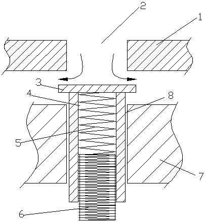
[0028] figure 1 It is a structural schematic diagram of the present invention, and the names of the parts in the figure: valve seat 1, vent hole 2, valve plate 3, lift channel 4, spring 5, limit post 6, valve cover 7, lift limiter hole 8. As can be seen in conjunction with the accompanying drawings, the air valve lift adjustment method includes the following steps:

[0029] Step 1: Set the limit column: connect the bottom of the lift channel of the air valve, set a limit column at the bottom of the lift channel, set external threads around the limit column, and set internal threads on the inner wall of the lift channel, The limit post is threadedly connected to the lift channel,...


PUM


Abstract

The invention discloses an air valve lift adjustment method. The air valve lift adjustment method includes the following operating steps that firstly, a limiting column is arranged, wherein the limiting column is arranged at the bottom of a lift channel; secondly, a spring is arranged, wherein the spring is located in the lift channel; thirdly, the spring is compressed, wherein when the spring isused and becomes fatigue, the limiting column is screwed; and fourthly, the spring is replaced, wherein the after excessive fatigue of the spring, the spring is replaced with a new spring. According to the air valve lift adjustment method, the limiting column can move up and down in the lift channel, and when the elasticity of the spring is weakened to a certain extent, the limiting column is screwed towards the lift channel by a certain distance to compensate for the weakened elasticity of the spring; and when the elasticity of the spring disappears seriously, the limiting column is disassembled, a new spring is arranged for replacement, an air valve can be reused, it is avoided that raw materials are replaced and wasted, and the using efficiency of the air valve is improved.

Description

technical field [0001] The invention relates to a method for adjusting the lift of an air valve, and belongs to the technical field of air valves. Background technique [0002] The gas valve is an important component on the compressor cylinder, which is responsible for the suction and discharge of gas. The traditional air valve is composed of valve seat, valve plate, spring, lift limiter, bolt and so on. [0003] After the traditional air valve is used for a period of time, the spring will be fatigued, the elastic force will be reduced, and the working performance of the air valve will be reduced, which will affect the normal operation of the compressor. The air valve can only be replaced, but the air valve is composed of multiple parts, all of which are metal The cost of materials is very high, and direct replacement is a waste of resources. [0004] The inventor has not yet found a technical solution to provide a solution to spring fatigue after searching. [0005] The ...

Claims


Application Information

Patent Timeline
Patent Type & Authority Applications(China)
IPC IPC(8): F04B39/10F04B39/14F04B49/10
CPCF04B39/1013F04B39/14F04B49/10
Inventor 钱国东
Owner WUXI HOUFA AUTOMATIC EQUIP CO LTD
Why Eureka
Try Eureka