Rotor cover shell structure inside rotating disk cavity and engine comprising same

A rotating disc and casing technology, applied to engine components, machines/engines, liquid fuel engines, etc., can solve the problems of increased airflow pressure loss, bleed air pressure reduction, etc., to reduce flow loss, increase airflow pressure, and simple structure Effect

Active Publication Date: 2018-02-23
INST OF ENGINEERING THERMOPHYSICS - CHINESE ACAD OF SCI
View PDF5 Cites 3 Cited by
  • Summary
  • Abstract
  • Description
  • Claims
  • Application Information

AI Technical Summary

Problems solved by technology

As the airflow moves toward the low-radius position, the airflow rotation ratio gradually increases, which will lead to an increase in the pressure loss of the airflow at the low-radius position inside the disk cavity, resulting in a decrease in the bleed air pressure downstream of the branch flow path, which has a negative effect on The influence of the pressure change law of the branch flow path will be very significant

Method used


Image

  • Rotor cover shell structure inside rotating disk cavity and engine comprising same
  • Rotor cover shell structure inside rotating disk cavity and engine comprising same

Examples


Embodiment Construction

[0022] The present invention will be further described in detail below in conjunction with the examples, the following examples are explanations of the present invention, and the present invention is not limited to the following examples.

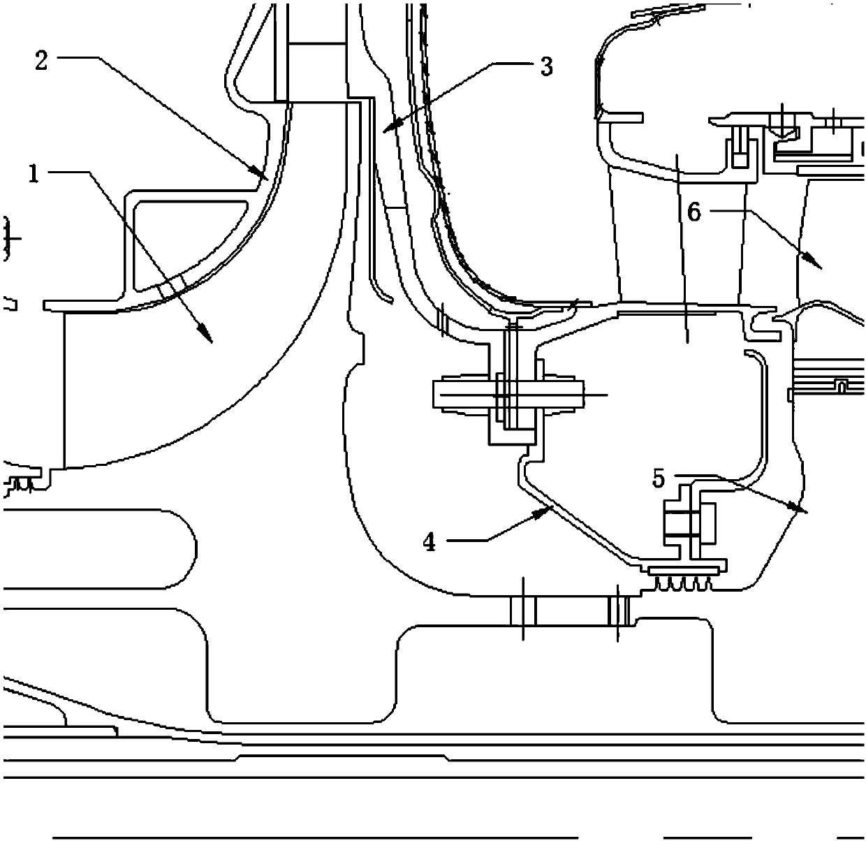
[0023] figure 1 It is a schematic diagram of the traditional disc cavity structure of a small aeroengine with a centrifugal compressor in the final stage, in which, 1 is the centrifugal compressor; 2 is the outer ring of the centrifugal compressor; 3 is the installation edge of the stator diffuser of the centrifugal compressor; 4 is Grate tooth sealing ring; 5 is a high-pressure turbine disc; 6 is a high-pressure turbine rotor blade. It can be seen that in this practical example, the airflow is introduced into the back cavity of the turntable along the root of the centrifugal impeller, and the back cavity of the turntable is composed of the centrifugal impeller disc of the centrifugal compressor 1, the mounting edge 3 of the stator diffuser...


PUM


Abstract

The invention relates to a bent-type rotor cover shell structure inside a centripetal inflow rotor-stator system rotating disk cavity. The bent-type rotor cover shell structure can be applied to the fields such as ground gas turbines and aero-engines. According to the unique characteristics of the bent-type rotor cover shell structure, the bent-type rotor cover shell structure formed through metalplates is applied to the low-radius position inside the rotor-stator system rotating disk cavity, through the light rotor cover shell structure, the rotating ratio of an air flow flowing inwards at the low-radius position is decreased, and thus the purpose that the flowing loss of the air flow in the inward flowing process is reduced is achieved. The bent-type rotor cover shell structure suitablefor the interior of the centripetal rotor-stator system rotating disk cavity has the effects that lightweight is achieved, the structure is simple, the processing cost is low, the rotating ratio of the air flow is reduced, and the air flow pressure in the disk cavity is increased, so that the great prospects of engineering application are achieved.

Description

technical field [0001] The invention belongs to the technical field of gas turbines and aeroengines, and relates to a rotor housing structure inside a rotating disk cavity, in particular to a method that can be applied in the rotating disk cavity of a centripetal aerostatic system to realize the air flow pressure of a branch flow path of a secondary air system Adjustable curved rotor case construction. Background technique [0002] In gas turbine and aero-engine air systems, it is a very common flow structure for gas to flow inward or outward through the rotating disk chamber, and the flow of rotating disk chambers in different positions and with different structures has different functions. For example: the rotating disc cavity at the end of the compressor is generally used for bleed air. This gas enters the rotating disc cavity through the root of the compressor rotor and flows inward to the center of the disc, and then passes through different flow paths to reach differen...

Claims


Application Information

Patent Timeline
Patent Type & Authority Applications(China)
IPC IPC(8): F04D29/42F04D29/44F02C7/04
Inventor 杜强刘军高金海柳光王沛刘红蕊胡嘉麟徐庆宗杨晓洁
Owner INST OF ENGINEERING THERMOPHYSICS - CHINESE ACAD OF SCI
Why Eureka
Try Eureka