Wire harness terminal crimping machine driving mechanism
A drive mechanism, wire harness terminal technology, applied in the direction of connection, circuit/collector parts, electrical components, etc., can solve the problems of unstable crimping process, uncontrollable crimping pressure, etc., to achieve reasonable structure, ensure reliability, Fast and reliable connection
- Summary
- Abstract
- Description
- Claims
- Application Information
AI Technical Summary
Problems solved by technology
Method used
Image
Examples
Embodiment 2
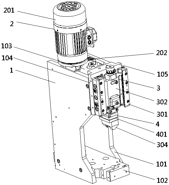
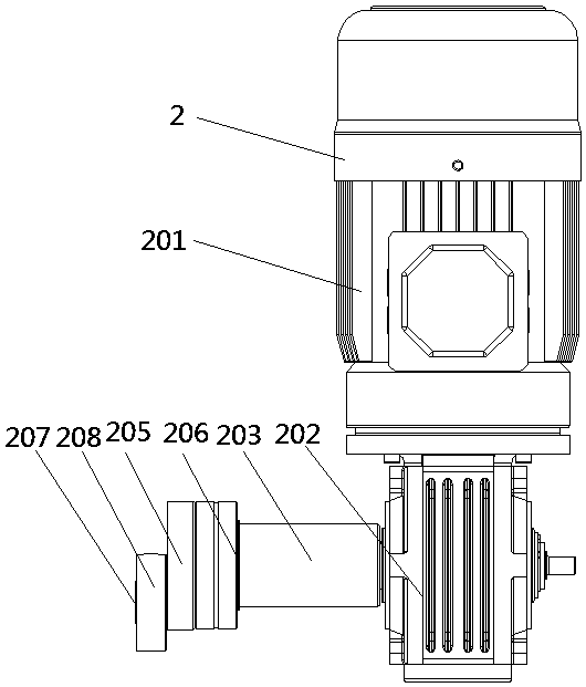
[0026]Embodiment 2, a driving mechanism of a wire harness terminal crimping machine, the slider 302 is a U-shaped slider with the opening facing downward, and a converter 5 is arranged in the notch of the U-shaped slider 302 , and the pressure The sensor 401 is arranged at the lower end of the converter 5, and the left and right sides of the converter 5 are provided with slots 501 for clamping the front and rear ends of the slider 302, and the front end of the converter 5 is provided with a clamping hole 504. Block 502, the position corresponding to converter 5 and clamping block 502 is provided with the fixed groove 503 that cooperates with clamping block 502, is provided with the first screw hole 505 of slide block that cooperates with fixed hole 504 in the fixed groove 503, uses pressing The screw 506 compresses the clamping block 502 and then the converter 5 is fixed on the slide block 302; the upper end surface of the slide block 302 is provided with a second screw hole 30...
Embodiment 3
[0028] Embodiment 3, a driving mechanism of a wire harness terminal crimping machine, the two sides of the bottom end of the converter 5 are provided with protruding spring seats 511, and the spring seats 511 are provided with spring seat holes 507, and the slider 302 The position corresponding to the spring seat hole 507 is provided with a third screw hole 508 of the slider, and the spring seat hole 507 is provided with a spring seat screw 509 that cooperates with the third screw hole 508 of the slider. The spring seat 511 and the slider 302 A pre-tightened compression spring 510 is arranged between the groove bottoms. Other structures of this embodiment are the same as those of Embodiment 2.
[0029] By setting the spring seat and the pre-tightened compression spring on the converter, the connection between the converter and the slider can be made more secure and reliable, avoiding shaking and affecting the crimping effect of the wire harness terminal, and further ensuring t...
Embodiment 4
[0030] Embodiment 4, a driving mechanism of a wire harness terminal crimping machine, a base 601 with a boss 606 is provided between the fine-tuning shaft 6 and the slider 302, and a groove 605 is provided corresponding to the slider 302 and the boss 604 A fine-tuning compression spring 602 and a flat washer 603 are arranged between the base 601 and the fine-tuning shaft 6, the flat washer 603 is arranged at the bottom of the base 601, and the fine-tuning compression spring 602 is arranged between the flat washer 603 and the outer end cap of the fine-tuning shaft 6 Between; the outer end cap of the fine-tuning shaft 6 is provided with an equal division dial 604 marking the adjustment distance of the fine-tuning shaft 6. The other structures of this embodiment are the same as those of Embodiment 2.
[0031] Setting a base for installing the fine-tuning shaft, and setting a fine-tuning compression spring and a flat washer in the base can provide a stable pre-tightening force for ...
PUM
 Abstract
Description
Claims
Application Information
 - R&D Engineer
- R&D Manager
- IP Professional
- Industry Leading Data Capabilities
- Powerful AI technology
- Patent DNA Extraction
Browse by: Latest US Patents, China's latest patents, Technical Efficacy Thesaurus, Application Domain, Technology Topic.
© 2024 PatSnap. All rights reserved.Legal|Privacy policy|Modern Slavery Act Transparency Statement|Sitemap


