Electrically-driven ultra-large-displacement well cementation equipment

A super-large, well-cementing technology, applied in the direction of mechanical equipment, clay preparation equipment, wellbore/well components, etc., can solve the problems of high noise, high fuel consumption, and large occupied volume of diesel engines, and achieve the reduction of torque converter settings, The effect of increasing operational safety and increasing layout space

Pending Publication Date: 2020-09-18
YANTAI JEREH PETROLEUM EQUIP & TECH CO LTD
View PDF0 Cites 113 Cited by
  • Summary
  • Abstract
  • Description
  • Claims
  • Application Information

AI Technical Summary

Problems solved by technology

The selection of diesel engine and torque converter is difficult, costly, and difficult to maintain. Moreover, diesel engine and torque converter are heavy and occupy a large volume, which is not conducive to the layout of the whole vehicle and restricts the selection of chassis. The cementing equipment depends on the chassis strong, while the diesel engine has high noise, large emissions, high fuel consumption, and pollutes the environment
Although electric drive cementing equipment has appeared at present, it is necessary to set up a vehicle-mounted power distribution cabinet, supply power through the power distribution cabinet, and provide power for the vehicle-mounted device through multiple motors, the wiring is complicated, and the cementing cost is high.
And because the temperature of the motor is high when it is working, multiple motors are scattered on the vehicle carrier, and the operator may be easily burned by accidental touch during cementing operation, which is dangerous

Method used


Image

  • Electrically-driven ultra-large-displacement well cementation equipment
  • Electrically-driven ultra-large-displacement well cementation equipment

Examples


Embodiment Construction

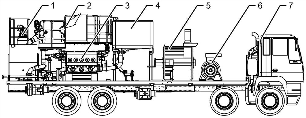
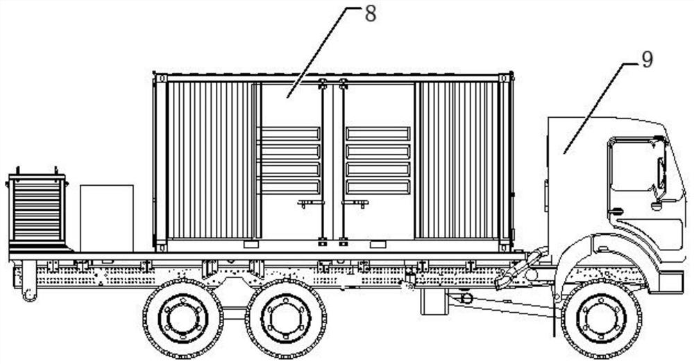
[0020] like figure 1 and 2 As shown, an electric drive ultra-large displacement cementing equipment includes a first loading body 7 and a second loading body 9, and the first loading body 7 is fixedly loaded with an auxiliary motor 6, a main motor 5, a clean water module 4, The pumping module 3, the control module 2, the hydraulic module and the mixing module 1, the first loading body 7 is also loaded with a lubrication module and an air circuit module, and the second loading body 9 is fixedly loaded with a frequency converter module 8, so The frequency converter module 8 supplies power for the auxiliary motor 6, the main motor 5, the control module 2, the lubrication module and the air circuit module loaded on the first loading body 7, and the main motor 5 provides power for the pumping module 3, The auxiliary motor 6 provides power for the clean water module 4 and the mixing module 1 through a hydraulic module. The main motor 5 is used to drive the pumping module 3, the to...


PUM


Abstract

The invention discloses electrically-driven ultra-large-displacement well cementation equipment. The electrically-driven ultra-large-displacement well cementation equipment comprises a first loading body and a second loading body; an auxiliary motor, a main motor, a clear water module, a pumping module, a control module, a hydraulic module and a mixing module are fixedly loaded on the first loading body; and a frequency converter module is fixedly loaded on the second loading body. The electrically-driven ultra-large-displacement well cementation equipment has the beneficial effects that the main motor is adopted to drive a plunger pump, torque converters are reduced, the layout space of the whole vehicle is increased, the auxiliary motor is adopted to drive a whole vehicle hydraulic system, and the number of driving motors is reduced; the frequency converter module and the well cementation equipment are loaded separately, the loading requirement is lowered, the structure is simpler, the occupied space is reduced, one frequency converter module can supply power to all the modules on the multiple first loading bodies at the same time, and use is flexible; and the main motor, the auxiliary motor and the hydraulic heat dissipation device are intensively distributed on the front portion of the first loading body, wiring is simple, connection is convenient, heat dissipation of equipment is intensively achieved, scalding accidents of workers in the operation process are avoided, and operation safety is improved.

Description

technical field [0001] The invention relates to the technical field of petroleum equipment, in particular to an electric drive super large displacement cementing equipment. Background technique [0002] Now the shale gas development technology is becoming more and more mature, the drilling depth of the well site is getting deeper and deeper, and the high-pressure, large-displacement operating environment can no longer be realized by conventional single-pump and double-pump cementing equipment. It is necessary to start multiple cementing equipment at the same time to meet the demand for larger displacement and higher pressure. When conventional cementing equipment is in operation, the power is driven by the on-board diesel engine through the torque converter through the transmission shaft to drive the plunger pump, and the vehicle chassis engine drives the hydraulic system of the vehicle. The selection of diesel engine and torque converter is difficult, costly, and difficult...

Claims


Application Information

Patent Timeline
Patent Type & Authority Applications(China)
IPC IPC(8): E21B33/13F04B17/03B28C5/08B28C7/12B28C7/16
CPCB28C5/08B28C5/0806B28C7/126B28C7/163E21B33/13F04B17/03
Inventor 王彦峰王吉华李恩杰刘仁王金张鹏远邹力抚李明升马灯刚吴张晔
Owner YANTAI JEREH PETROLEUM EQUIP & TECH CO LTD
Why Eureka
Try Eureka