
Main and standby power supply switching circuit

A technology for switching circuits and main and backup power supplies, which is applied to circuit devices, emergency power supply arrangements, emergency protection circuit devices, etc., and can solve problems such as loss, easy arc generation, and equipment damage

Pending Publication Date: 2018-02-23
ZHEJIANG XIANDAI ELECTRIC
View PDF0 Cites 1 Cited by
  • Summary
  • Abstract
  • Description
  • Claims
  • Application Information

AI Technical Summary

Problems solved by technology

[0002] The existing power switching circuit uses a four-way relay for each power supply, two of which are normally open, and the other two are respectively connected to the neutral line and the live line, so that when the relay is closed, the two armatures are separated from the normally open position. It is attracted to the zero line and live line end, so that the circuit can be energized, but the position of the zero line and the live line of this circuit is very close, and it is easy to generate an arc at the moment of electric shock when the relay is closed, so it is easy to burn out the whole circuit , causing equipment damage, or even serious loss

Method used


Image

  • Main and standby power supply switching circuit
  • Main and standby power supply switching circuit
  • Main and standby power supply switching circuit

Examples


Embodiment Construction

[0021] The present invention will be described in further detail below in conjunction with the embodiments given in the accompanying drawings.

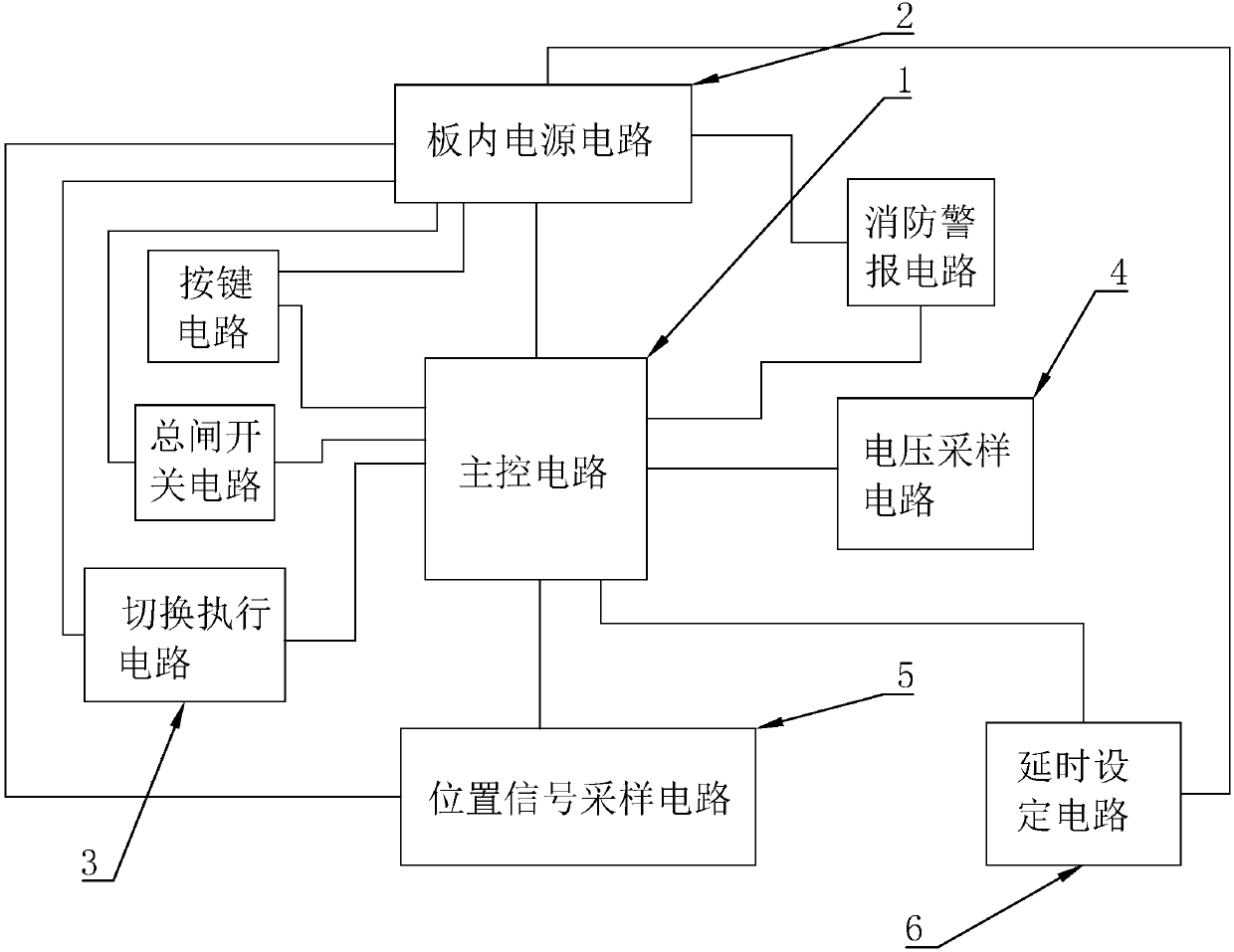
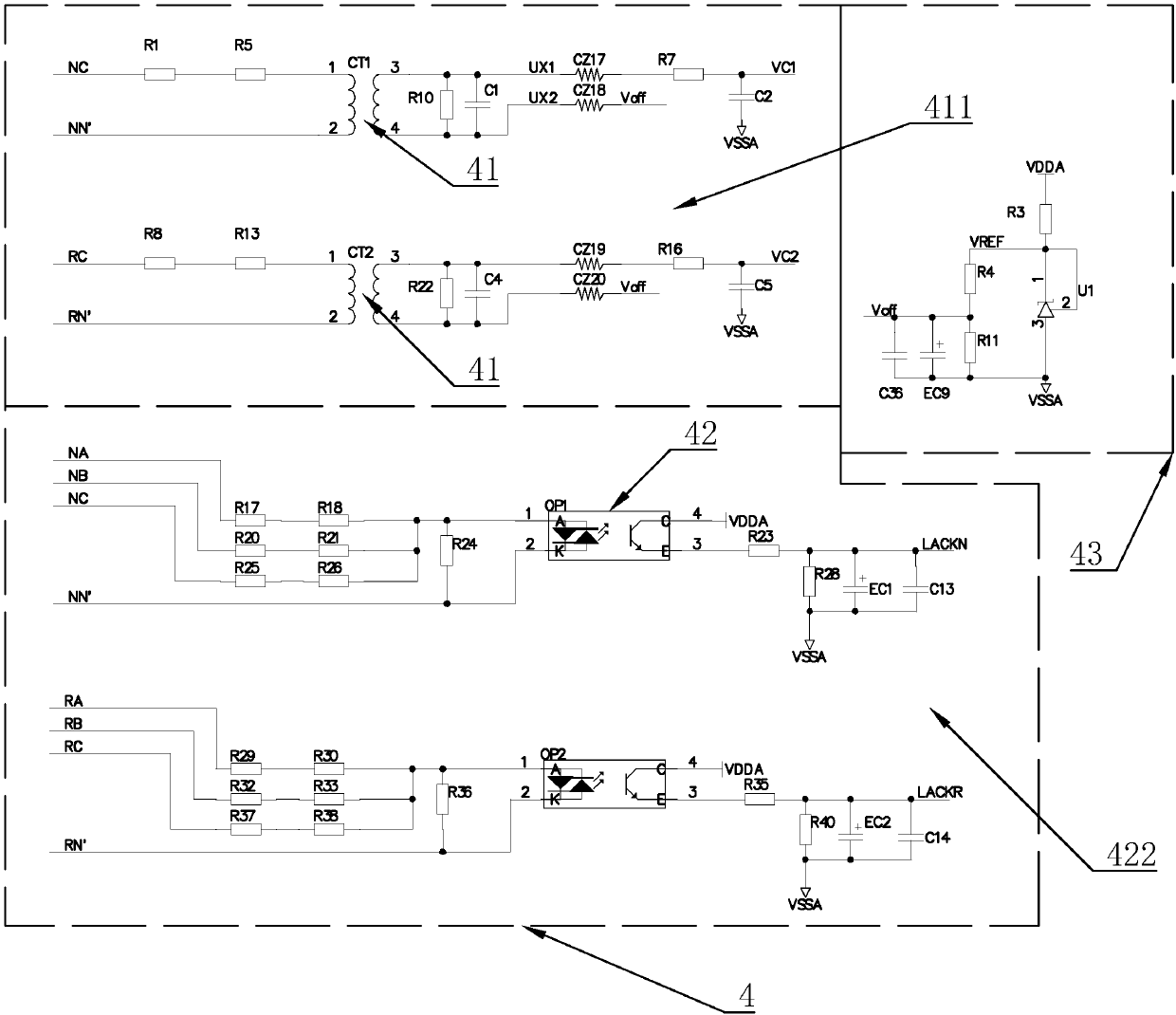
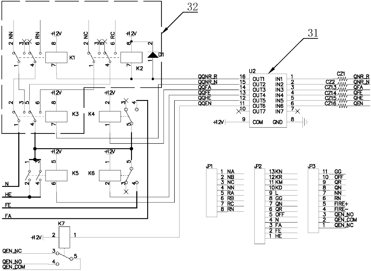
[0022] refer to Figure 1-6 As shown, a main and standby power switching circuit of this embodiment includes a main control circuit 1, an on-board power supply circuit 2 and a switching execution circuit 3, the on-board power supply circuit 2 is coupled to the switching execution circuit 3, and the on-board The internal power supply circuit 2 is also coupled with the main control circuit 1, the on-board power supply circuit 2 provides working power to the main control circuit 1 and the switching execution circuit 3, and the main control circuit 1 is coupled with the switching execution circuit 3 to send switching signal, the switching execution circuit 3 receives the switching signal and switches the action, the switching execution circuit 3 includes a power selection circuit 32 and a switch drive chip 31, the power selection circuit ...


PUM


Abstract

The invention discloses a main and standby power supply switching circuit. An arranged inboard power circuit can provide a switching execution circuit and a main control circuit with adaptive workingvoltage, so that the main control circuit can control a switch drive chip; and through the arrangement of the switch drive chip, control of a zero line control switch and a fire line control switch can be more convenient, and the circuit is simplified. Therefore, compared with an existing power supply switching circuit of which a double-pole double-throw relay is connected to zero lines and fire lines of a main power supply and a standby power supply at the same time, the main and standby power supply switching circuit disclosed by the invention has the advantages that the zero line control switch outputs a main circuit zero line or a standby circuit zero line, and the fire line control switch outputs a main circuit fire line or a standby circuit fire line, so that power lines can be far away from each other; and furthermore, the fire line control switch only controls on / off of the fire lines of the main power supply and the standby power supply, and the zero line control switch only controls on / off of the zero lines of the main power supply and the standby power supply, so that the relay is prevented from generating an electric arc.

Description

technical field [0001] The power switching circuit of the present invention is specifically a main and standby power switching circuit. Background technique [0002] The existing power switching circuit uses a four-way relay for each power supply, two of which are normally open, and the other two are respectively connected to the neutral line and the live line, so that when the relay is closed, the two armatures are separated from the normally open position. It is attracted to the zero line and live line end, so that the circuit can be energized, but the position of the zero line and the live line of this circuit is very close, and it is easy to generate an arc at the moment of electric shock when the relay is closed, so it is easy to burn out the whole circuit , causing equipment damage, or even serious losses. Contents of the invention [0003] Aiming at the deficiencies in the prior art, the purpose of the present invention is to provide an executive circuit in which t...

Claims


Application Information

Patent Timeline
Patent Type & Authority Applications(China)
IPC IPC(8): H02J9/06H02H3/08
CPCH02H3/085H02J9/061H02J9/068Y04S20/20Y02B70/30
Inventor 方彬鹏苏阳梁玉乐
Owner ZHEJIANG XIANDAI ELECTRIC
Learn More