Beamforming training method, terminal and base station

A training method and beamforming technology, applied in the field of communication, can solve problems such as the inability to flexibly adjust the number of beam training beams

Active Publication Date: 2018-02-23
DATANG MOBILE COMM EQUIP CO LTD
View PDF5 Cites 6 Cited by
  • Summary
  • Abstract
  • Description
  • Claims
  • Application Information

AI Technical Summary

Problems solved by technology

[0012] In view of this, the present invention provides a beamforming training method, terminal and base station, which are used to solve the probl

Method used


Image

  • Beamforming training method, terminal and base station
  • Beamforming training method, terminal and base station
  • Beamforming training method, terminal and base station

Examples


Embodiment 1

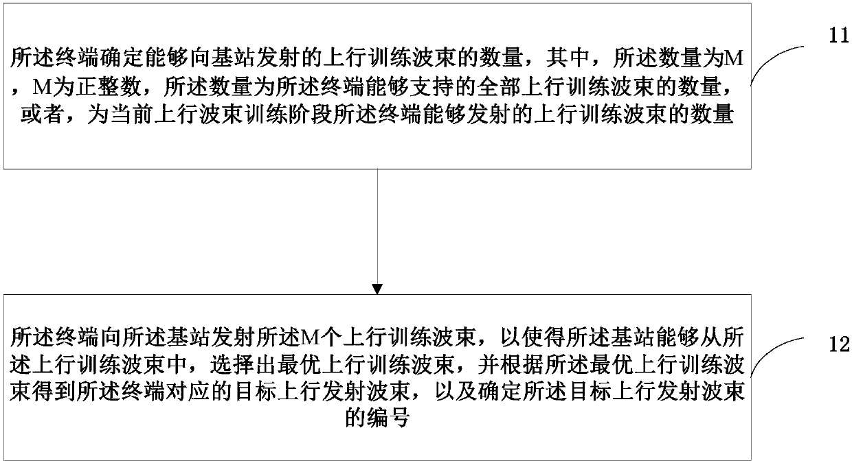
[0130] Please refer to figure 1 , figure 1 It is a schematic flow chart of a beamforming training method according to Embodiment 1 of the present invention. The beamforming training method is applied to a terminal, including:

[0131] Step 11: The terminal determines the number of uplink training beams that can be transmitted to the base station, where the number is M, M is a positive integer, and the number is the number of all uplink training beams that the terminal can support, or, is the number of uplink training beams that the terminal can transmit in the current uplink beam training phase;

[0132] Wherein, M is usually a positive integer greater than 1.

[0133] Step 12: The terminal transmits the M uplink training beams to the base station, so that the base station can select an optimal uplink training beam from the uplink training beams, and select an optimal uplink training beam according to the optimal uplink training beam The target uplink transmission beam co...

Embodiment 2

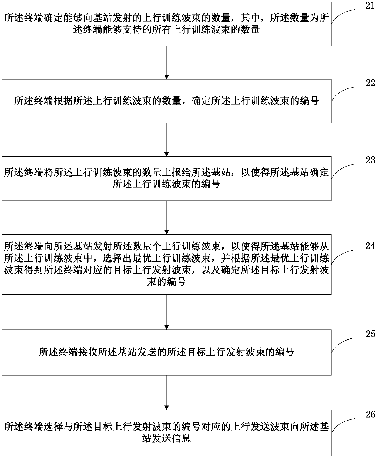
[0138] Please refer to figure 2 , figure 2 It is a schematic flow chart of the beamforming training method in Embodiment 2 of the present invention, the beamforming training method is applied to the terminal, including:

[0139] Step 21: The terminal determines the number of uplink training beams that can be transmitted to the base station, where the number is the number of all uplink training beams that the terminal can support, the number is M, and M is a positive integer, the The number of all uplink training beams that the terminal can support is one of the capabilities of the terminal;

[0140] Step 22: The terminal determines the serial number of the uplink training beam according to the number of the uplink training beam;

[0141]Step 23: The terminal reports the number of the uplink training beams to the base station, so that the base station determines the number of the uplink training beams.

[0142] Step 24: The terminal transmits the M uplink training beams to...

Embodiment 3

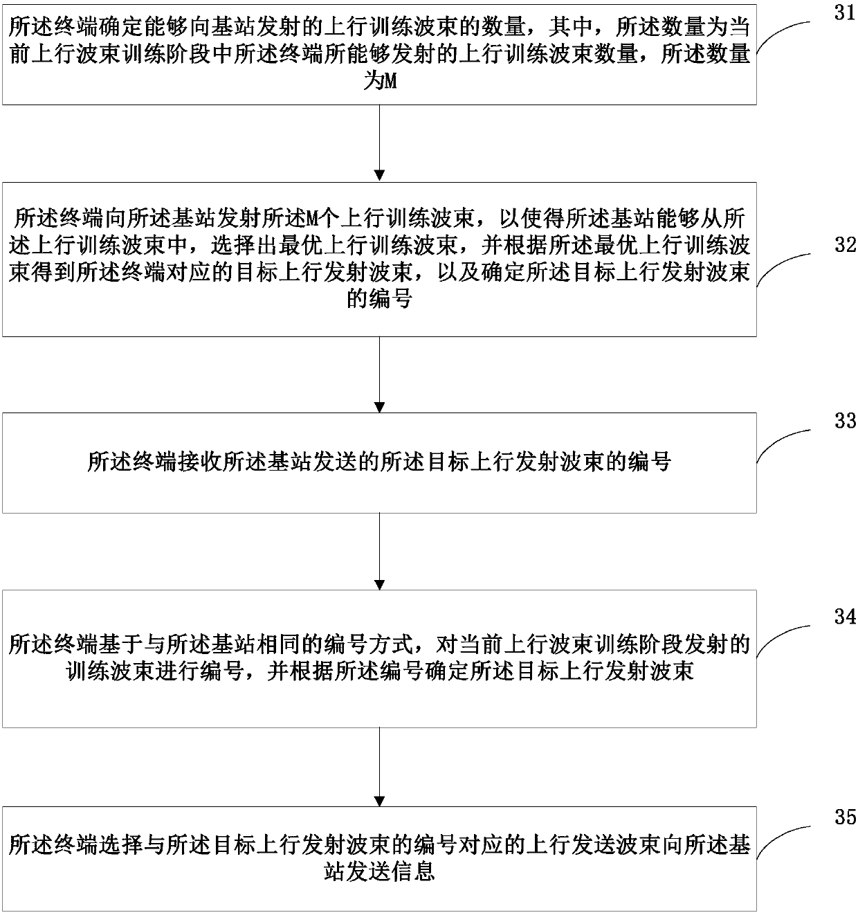
[0156] Please refer to image 3 , image 3 It is a schematic flow chart of the beamforming training method in Embodiment 3 of the present invention. The beamforming training method is applied to the terminal, including:

[0157] Step 31: The terminal determines the number of uplink training beams that can be transmitted to the base station, where the number is the number of uplink training beams that the terminal can transmit in the current uplink beam training phase, and the number is M, where M is positive integer;

[0158] The number of uplink training beams that the terminal can transmit in the current uplink beam training phase may be determined by the following factors:

[0159] (1) Determined according to the resource configuration in the current uplink beam training phase and / or the beam switching capability of the terminal; wherein, the beam switching capability of the terminal is one of the capabilities of the terminal;

[0160] or

[0161] (2) agreed upon by the...


PUM


Abstract

The invention provides a beamforming training method, a terminal and a base station. The beamforming training method comprises the steps that the terminal determines a quantity of uplink training beams that are sent to the base station, wherein the quantity refers to a quantity of all uplink training beams which the terminal supports, the quantity is M that is a positive integer, or, the quantityis a quantity of uplink training beams which the terminal sent in a current uplink beam training stage; and the terminal sends M uplink training beams to the base station, so as to enable the base station to select an optimal uplink training beam from the uplink training beams, obtain a target uplink emission beam corresponding to the terminal according to the optimal uplink training beam and determine a number of the target uplink emission beam. Through adoption of the method, the quantity of beams used in beam training can be adjusted flexibly according to the terminal capability and specific application scenes.

Description

technical field [0001] The present invention relates to the field of communication technology, in particular to a beamforming training method, a terminal and a base station. Background technique [0002] In view of the important role of MIMO (Multiple-Input Multiple-Output) technology in improving the peak rate and system spectrum utilization, LTE (Long Term Evolution, Long Term Evolution) / LTE-A (LTE-Advanced) and other wireless access All input technical standards are built on the basis of MIMO+OFDM (Orthogonal Frequency Division Multiplexing, Orthogonal Frequency Division Multiplexing) technology. The performance gain of MIMO technology comes from the spatial freedom obtained by multi-antenna systems. Therefore, one of the most important evolution directions of MIMO technology in the standardization development process is the expansion of dimensions. In LTErel-8, MIMO transmission of up to 4 layers can be supported. Rel-9 focuses on enhancing MU-MIMO technology. TM (Tran...

Claims


Application Information

Patent Timeline
IPC IPC(8): H04B7/06
CPCH04B7/0617H04B7/06
Inventor 苏昕高秋彬陈润华塔玛拉卡·拉盖施宋扬李传军王蒙军杨宇李辉黄秋萍
Owner DATANG MOBILE COMM EQUIP CO LTD
Why Eureka
Try Eureka