Safety Devices for Syringes

A technology of safety devices and syringes, applied in the direction of syringes, hypodermic injection devices, infusion sets, etc., can solve problems such as injuries, inability to administer drugs, and unusable syringes

A technology of safety devices and syringes, applied in the direction of syringes, hypodermic injection devices, infusion sets, etc., can solve problems such as injuries, inability to administer drugs, and unusable syringes

CN107735129BActive Publication Date: 2020-07-28GERRESHEIMER REGENSBURG GMBH +1

Image

  • Safety Devices for Syringes
  • Safety Devices for Syringes
  • Safety Devices for Syringes

Examples


Embodiment Construction

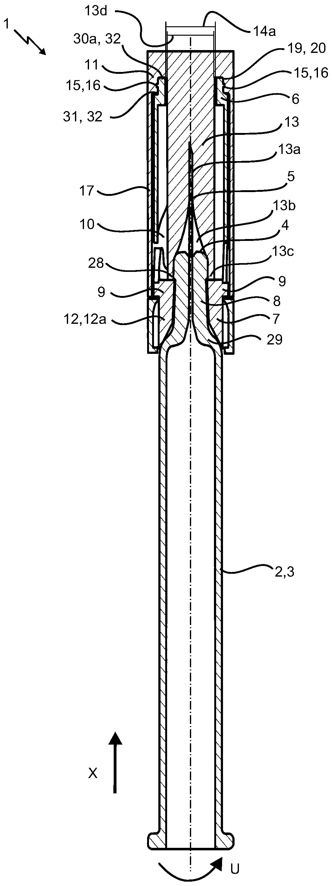
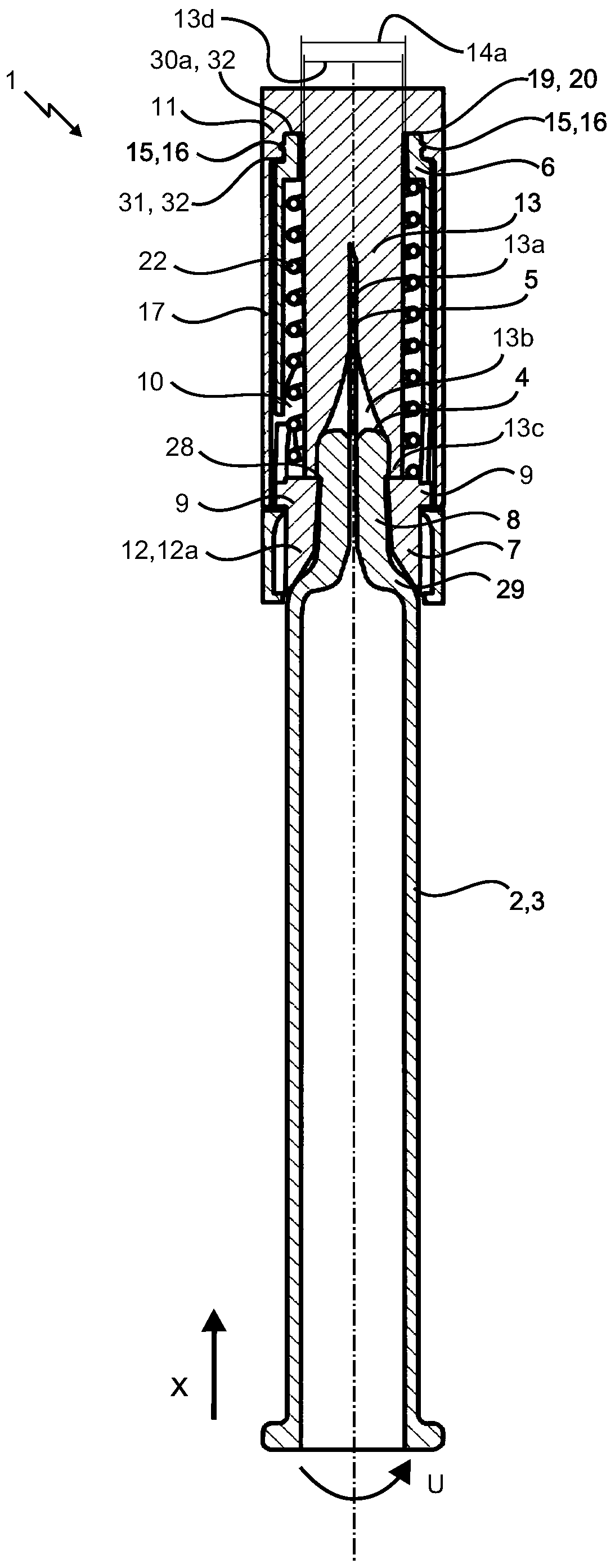
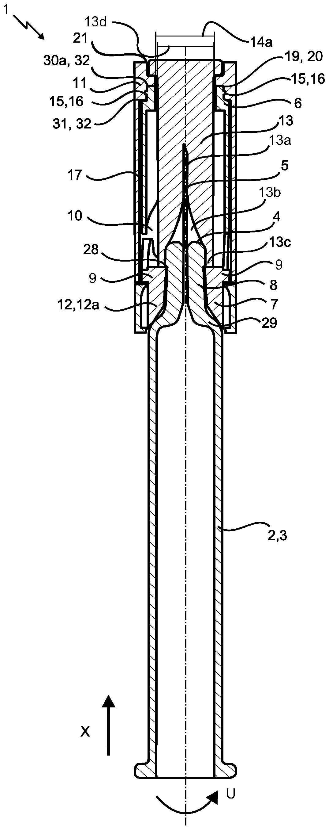
[0033] Figure 1-4 Shown is a syringe (2) comprising a safety device (1) for avoiding poking according to various embodiments. The syringe (2) comprises a syringe body (3) designed as a hollow cylinder. The syringe body comprises a distal region (8) having a distal end (4). A piercing mechanism (5) is provided at the distal end (4). The piercing mechanism (5) is connected to the cavity of the syringe body (3) through a hole in the distal region (8), so that when the syringe (2) is applied, the medium to be injected can pass from the cavity through the piercing mechanism (5) Appear. The distal region (8) is designed as a tapered end portion with a smaller outer diameter than the syringe body (3). The syringe also includes a transition region (29) where the outer diameter of the syringe body meets the outer diameter of the tip portion. Furthermore, a protrusion (28) is provided in the distal region.

[0034] Furthermore, a puncture-avoiding safety device (1) for a syringe ...


PUM


Abstract

The present invention relates to a safety device for avoiding stab wounds for a syringe comprising a syringe body and a piercing mechanism arranged at the distal end of the syringe body. The safety device includes a sleeve element extending in the axial direction (X) and at least partially surrounding the piercing mechanism and the syringe body, and also includes a sleeve element disposed on the distal region of the syringe body and locking the safety device in the axial direction (X). A collar element comprising at least one guide projection which engages in at least one guide rail of the sleeve element. The safety device further comprises a cap element arranged to be at least partially seatable on the sleeve element and by means of which the sleeve element can be locked with respect to movement of the syringe body relative to the sleeve element.

Description

technical field [0001] The present invention relates to a safety device for avoiding stab wounds for a syringe having a syringe body and a piercing mechanism arranged at the distal end of the syringe body, the safety device comprising a The sleeve element of the threading mechanism and the syringe body, also includes a harness element arranged on the distal end region of the syringe body and locks the safety device in the axial direction (X), the harness element includes at least one guide protrusion, The guide protrusion engages in at least one guide rail of the sleeve element. Background technique [0002] Common safety devices for avoiding stab wounds are known. The use of such a safety device is particularly meaningful for prefilled syringes. Handling of this syringe is very simple as there is no need to transfer media into the syringe prior to application. In addition, the possibility of using the wrong drug is low, even in an emergency. The syringe is currently the...

Claims


Application Information

Patent Timeline
28 Jul 2020
Publication
CN107735129B
IPC
A61M5/32
CPC
A61M5/3202; A61M5/326; A61M5/3272; A61M2005/3118; A61M2005/312; A61M2005/3107; A61M2005/3267; A61M5/002
Inventors
弗兰克·威特兰德; 马克西米兰·沃格尔