Depth camera shooting device, manufacturing method, display panel and manufacturing method and device

A device manufacturing method and depth imaging technology, which are applied in radiation control devices, electric solid state devices, semiconductor devices, etc., can solve the problems of high cost, inflexible use, and difficulty in miniaturization, so as to avoid interference, low cost, and reduce cost effect

Active Publication Date: 2018-02-27
BOE TECH GRP CO LTD
View PDF7 Cites 9 Cited by
  • Summary
  • Abstract
  • Description
  • Claims
  • Application Information

AI Technical Summary

Problems solved by technology

The two core components usually appear in the form of two module devices, and it is usually difficult to achieve miniaturization, which makes the cost relatively high and the use is not flexible enough

Method used


Image

  • Depth camera shooting device, manufacturing method, display panel and manufacturing method and device
  • Depth camera shooting device, manufacturing method, display panel and manufacturing method and device
  • Depth camera shooting device, manufacturing method, display panel and manufacturing method and device

Examples


Embodiment Construction

[0044] The application will be further described in detail below in conjunction with the accompanying drawings and embodiments. It should be understood that the specific embodiments described here are only used to explain related inventions, rather than to limit the invention. It should also be noted that, for ease of description, only parts related to the invention are shown in the drawings.

[0045] It should be noted that, in the case of no conflict, the embodiments in the present application and the features in the embodiments can be combined with each other. The present application will be described in detail below with reference to the accompanying drawings and embodiments.

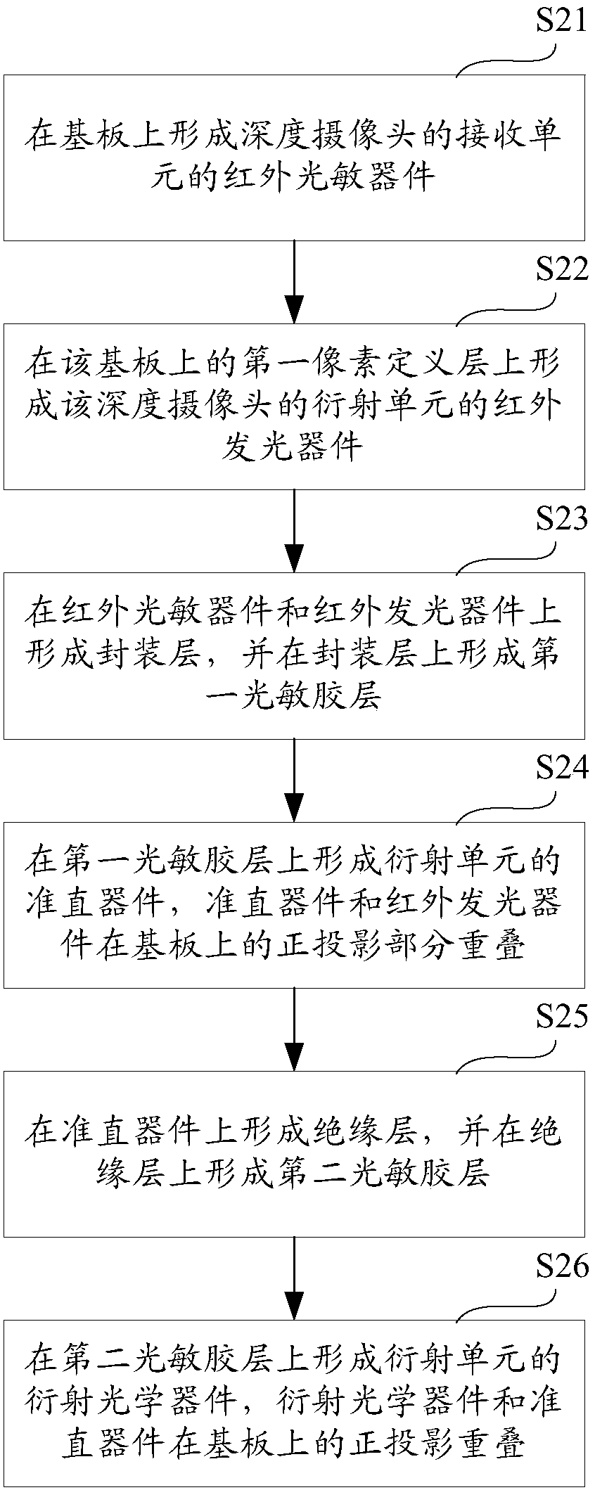
[0046] figure 2 It is a flow chart of a manufacturing method of a depth imaging device provided by an embodiment of the present invention.

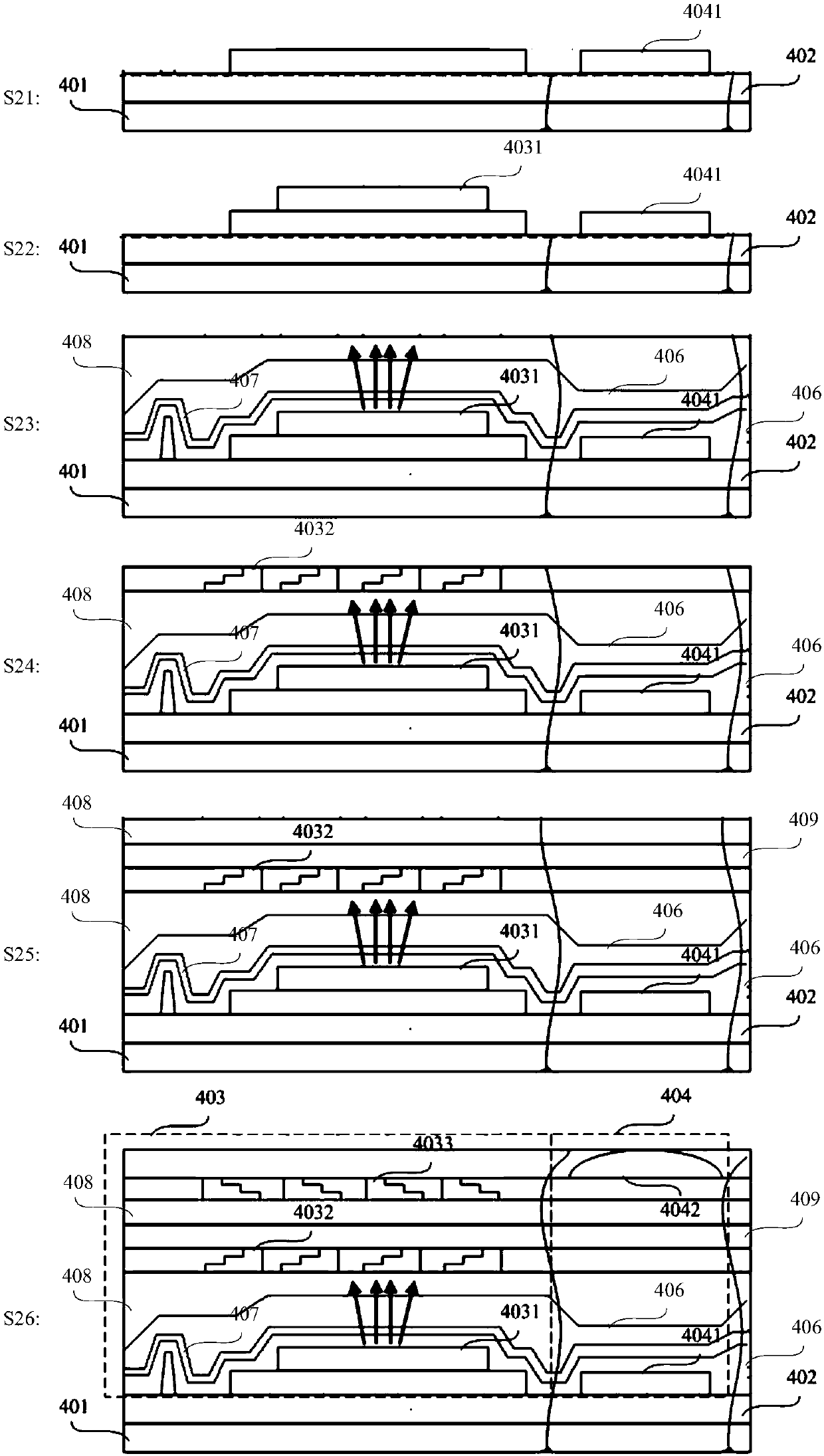
[0047] Such as figure 2 As shown, in this embodiment, a method for manufacturing a depth imaging device provided by the present invention includes:

[0...


PUM


Abstract

The invention provides a depth camera shooting device, a manufacturing method thereof, a display panel and a manufacturing method and device thereof. The manufacturing method of the depth camera shooting device comprises the steps that an infrared photosensitive device of a receiving unit of a depth camera is formed on a substrate; an infrared light-emitting device of a diffraction unit of the depth camera is formed on a first pixel definition layer on the substrate; a packaging layer is formed on the infrared photosensitive device and the infrared light-emitting device, and a first photosensitive adhesive layer is formed on the packaging layer; a collimation device of the diffraction unit on the first photosensitive adhesive layer, and orthographic projections of the collimation device and the infrared light-emitting device are partially overlapped on the substrate; an insulating layer is formed on the collimation device, and a second photosensitive adhesive layer is formed on the insulating layer; a diffraction optical device of the diffraction unit is formed on the second photosensitive adhesive layer, and the orthographic projections of the diffractive optical device and the collimation device are overlapped on the substrate. The miniaturized depth camera is integrated on the substrate, so that depth information acquisition is achieved at a relatively low cost.

Description

technical field [0001] The present application relates to the technical field of display devices, in particular to a depth imaging device and a manufacturing method thereof, a display panel and a manufacturing method thereof, and a device. Background technique [0002] With the development of 3D technology, more and more technical applications such as stereoscopic display, machine vision, and satellite remote sensing need to obtain the depth information of the scene. At present, the technical method usually used is to use the depth camera to obtain the depth information of the target in the camera field of view. . [0003] At present, there are three main architectures for depth cameras, namely binocular stereo vision method, time-of-flight (TOF) method and structured light method. [0004] The binocular stereo vision method uses the stereo vision of two lenses to measure the depth of the scene. The camera emits light waves to illuminate the three-dimensional scene, and the...

Claims


Application Information

Patent Timeline
Patent Type & Authority Applications(China)
IPC IPC(8): H01L27/146G06V10/143
CPCH01L27/14683H01L27/14685H01L27/1469G06F3/042G06F3/017G06F1/1626G06F1/1637G06F1/1686G06F3/0304G06V20/64G06V40/28G06V10/143G06F3/0421G06F3/04883
Inventor 王鹏鹏王海生丁小梁郑智仁韩艳玲李扬冰曹学友刘伟张平
Owner BOE TECH GRP CO LTD
Why Eureka
Try Eureka