

End plate structure of fuel cell stack
A fuel cell stack and end plate technology, applied to fuel cells, circuits, electrical components, etc., can solve problems such as increased power generation costs, hidden safety hazards, energy waste, etc., and achieve the effects of saving energy, ensuring safe use, and preventing air leakage
- Summary
- Abstract
- Description
- Claims
- Application Information
AI Technical Summary
Problems solved by technology
Method used
Image


Examples
Embodiment
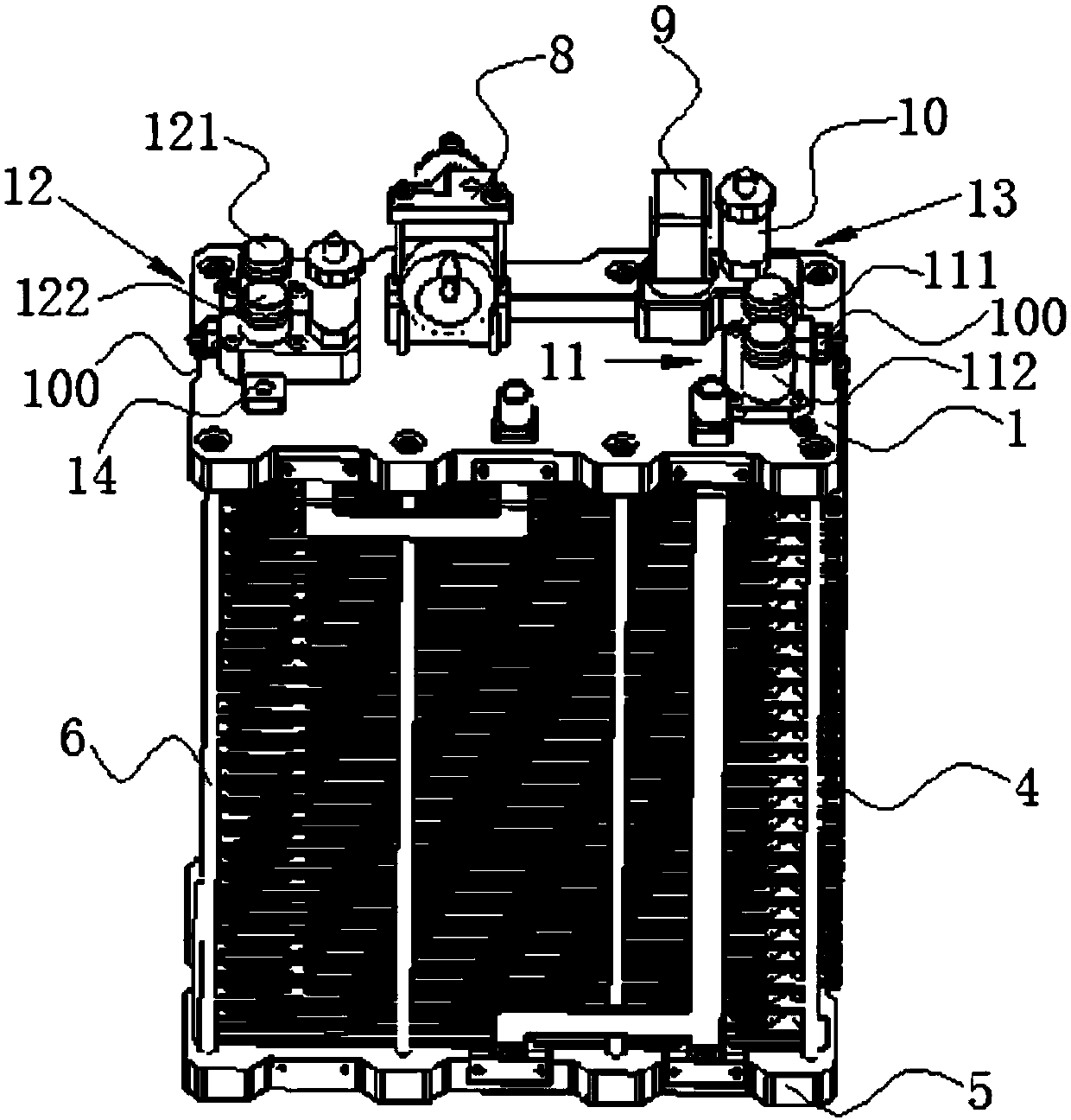
[0024] Embodiment: a fuel cell stack end plate structure, such as Figure 1-Figure 3 As shown, it includes an upper end plate 1, an insulating plate 2, a collector plate 3, a stack body 4 and a lower end plate 5, the upper end plate 1 and the lower end plate 5 are parallel to each other, and the upper end plate 1 and the lower end plate 5, two insulating plates 2 are arranged between them, two collector plates 3 are arranged between the two insulating plates 2, and the stack body is arranged between the two collector plates 3 4;
[0025] It also includes several insulating fixing rods 6 located on the periphery of the stack body, the two ends of the insulating fixing rods 6 are respectively connected to the nuts 7 of the upper end plate 1 and the nuts 7 of the lower end plate 5, and the nuts of the nuts 7 The inner surface has internal threads matching the external threads at both ends of the insulating fixing rod 6;
[0026] The upper end plate 1 has a first mounting seat 1...
PUM
 Abstract
Description
Claims
Application Information