Electronic handcuffs with alarming function

A technology of handcuffs and electronics, which is applied in the direction of handcuffs, radio wave measurement system, satellite radio beacon positioning system, etc. It can solve the problems of low safety performance, single structure and function, and inability to ensure the contact of high-voltage shock pads.

Inactive Publication Date: 2018-03-02
四川久远新方向智能科技有限公司
0 Cites 1 Cited by

AI-Extracted Technical Summary

Problems solved by technology

The handcuffs most used at present are only mechanical handcuffs with simple structure and single function. The threat of ordinary handcuffs to criminal suspects is also limited. Low
The existing electronic handcuffs cannot...

Abstract

The invention discloses a pair of electronic handcuffs with an alarming function. Each of the handcuffs is characterized by comprising a handcuff body and a core module; the handcuff body comprises afixed handcuff ring, a movable handcuff ring and a bayonet lock; the core module comprises a crash sensor, a pulse sensor, a pressure sensor, a high voltage generating module, a high voltage shock piece, a microcontroller unit, a micro-driver unit, a storage battery, a wireless charging module, a loudspeaker, a display, a wire communication module and a sound-light alarm module; the pressure sensor is configured to the inner side of the fixed handcuff ring and is connected to the microcontroller for detecting the pressure between the fixed handcuff ring and a wrist; the control signal output end of the microcontroller is connected to the loudspeaker, and the microcontroller is connected to the high voltage shock piece through the high voltage generator; the bayonet lock is located on the fixed handcuff ring for fixing the movable handcuff ring on the fixed handcuff ring. The wireless communication module is connected to the microcontroller for data transmission between the microcontroller and other terminal equipment.

Application Domain

HandcuffsSatellite radio beaconing

Technology Topic

Data transmissionLoudspeaker +12

Image

  • Electronic handcuffs with alarming function

Examples

  • Experimental program(1)

Example Embodiment

[0010] In order to make the purpose, technical solutions and advantages of the embodiments of the invention clearer, the technical solutions in the embodiments of the present invention will be clearly and completely described below in conjunction with the accompanying drawings in the embodiments of the present invention. Obviously, the described embodiments are Some, but not all, embodiments of the invention. The components of the embodiments of the invention generally described and illustrated in the figures herein may be arranged and designed in a variety of different configurations. Based on the embodiments of the present invention, all other embodiments obtained by persons of ordinary skill in the art without creative efforts fall within the protection scope of the present invention.
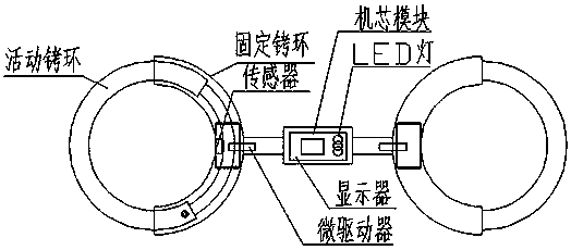
[0011] This embodiment provides an electronic handcuff with an alarm function, which is characterized in that: it includes a handcuff body and a core module; the handcuff body includes a fixed ring, a movable ring, and a bayonet pin; the core module includes a collision sensor , pulse sensor, pressure sensor, high-voltage generating module, high-voltage electric shock sheet, microcontroller unit, micro-drive unit, battery, wireless charging module, speaker, display, wireless communication module, sound and light alarm module; the pressure sensor is configured in On the inside of the fixed handcuff ring, the pressure sensor is connected to the microcontroller to detect the pressure on the fixed handcuff ring and the wrist; the microcontroller control signal output terminal is connected to the speaker, and the microcontroller is connected to the high-voltage electric shock sheet through the high-voltage generator; The bayonet is located on the fixed ring and is used to fix the movable ring on the fixed ring; the wireless communication module is connected to the microcontroller for data transmission with other terminal devices; the sound and light alarm module is connected to the The output terminals of the microcontroller are connected, including an audio amplifier circuit and an LED flashing circuit connected to LED lights of different colors, which are respectively used for collision alarm, over-pulse alarm and over-pressure alarm.
[0012] Preferably, the micro-driver module includes a first micro-driver and a second micro-driver; the first micro-driver is connected to the movable shackle ring for adjusting the position of the movable shackle ring; the second micro-driver is connected to the detent, Used to adjust the position of the detent.
[0013] Preferably, when the data detected by the collision sensor exceeds the collision setting threshold, or the pulse data detected by the pulse sensor reaches the pulse setting threshold, the controller drives the active handcuffs to contract through the first micro-driver, and the pulse data detected by the pulse sensor When the normal value is reached, the controller drives the bayonet through the second micro-driver to fix the electronic handcuffs, and realizes an alarm through the light-emitting alarm module.
[0014] Preferably, when the pressure data measured by the pressure sensor is less than the set threshold, or the pulse data detected by the pulse sensor reaches the pulse set threshold, the controller outputs a valid signal to the high pressure generating module.
[0015] Preferably, the electronic handcuffs also include a Beidou positioning module and a GPS positioning module, which are arranged in the case and connected to the input terminal of the microprocessor.
[0016] When the criminal uses violent actions, when the collision sensor detects that the acceleration data is too high, an alarm will be issued, and the microcontroller unit controls the high-voltage generating module to shock the criminal through the high-voltage electric shock sheet.
[0017] In the description of the present invention, it should be noted that the orientation or positional relationship indicated by the terms "center", "upper", "lower", "left", "right", "inner" and "outer" are based on the attached The orientation or positional relationship shown in the figure, or the conventional orientation or positional relationship of the utility model product in use, is only for the convenience of describing the present invention and simplifying the description, rather than indicating or implying that the referred device or element must have Certain orientations, constructed and operative in certain orientations, therefore are not to be construed as limitations on the invention. In addition, the terms "first", "second", "third", etc. are only used for distinguishing descriptions, and should not be construed as indicating or implying relative importance.
[0018] In the description of the present invention, it should also be noted that, unless otherwise clearly specified and limited, the terms "setting", "installation" and "connection" should be interpreted in a broad sense, for example, it can be a fixed connection or an optional connection. Disconnected, or integrally connected; either mechanical or electrical.

PUM

no PUM

Description & Claims & Application Information

We can also present the details of the Description, Claims and Application information to help users get a comprehensive understanding of the technical details of the patent, such as background art, summary of invention, brief description of drawings, description of embodiments, and other original content. On the other hand, users can also determine the specific scope of protection of the technology through the list of claims; as well as understand the changes in the life cycle of the technology with the presentation of the patent timeline. Login to view more.
Why Eureka
Try Eureka