Anti-looseness conjoined cap for bolts

A bolt and anti-loosening technology, applied in the directions of bolts, screws, nuts, etc., can solve the problems of low driving safety factor, high labor intensity, and large workload, and achieve the effect of wide applicability, simple structure, and preventing bolts from falling off.

Pending Publication Date: 2018-03-02
常润华
View PDF0 Cites 0 Cited by
  • Summary
  • Abstract
  • Description
  • Claims
  • Application Information

AI Technical Summary

Problems solved by technology

[0002] As is known, high-speed rail, subway, urban rail and ordinary railway tracks all need bolts to be fixed on spring bars (also known as compression springs or springs). The parts are divided into two, and two or three bolts are installed on one half of the fastener on one side of the track. Because the movement of high-speed rail, subway, urban rail and ordinary rail will bring vibrations of different amplitudes to the rail, the installation The bolts on the fasteners will loosen or even fall off after a period of time due to vibration. The staff need to carry out frequent inspections. During inspections, each bolt needs to be tapped to determine whether the bolts are loose and tighten the loose bolts in sequence. Not only the workload is heavy, but also the operation is frequent and the labor intensity is high
Loose bolts lead to low driving safety factor. Therefore, it is a basic demand of those skilled in the art to propose an anti-loosening cap that prevents bolts from loosening.

Method used


Image

  • Anti-looseness conjoined cap for bolts
  • Anti-looseness conjoined cap for bolts
  • Anti-looseness conjoined cap for bolts

Examples


Embodiment Construction

[0021] The present invention can be explained in detail through the following examples, and the purpose of disclosing the present invention is to protect all technical improvements within the scope of the present invention.

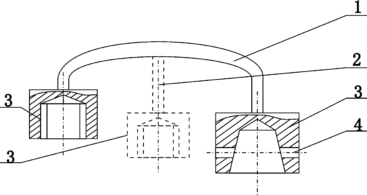
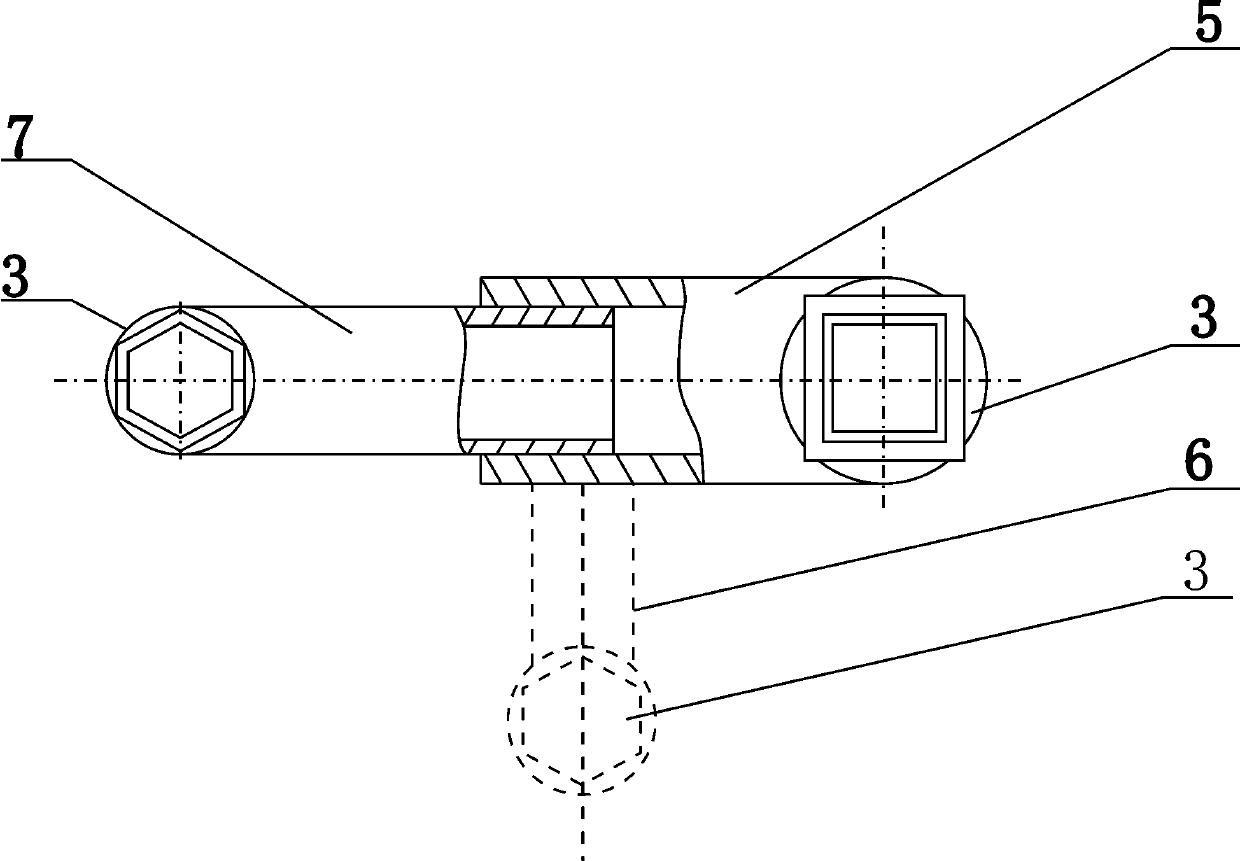
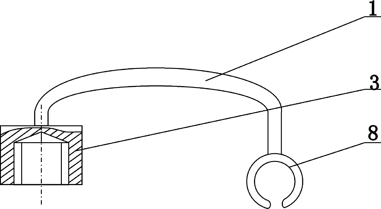
[0022] combined with Figure 1-4 Bolt anti-loosening conjoined caps, including connecting rod 1 and sleeve 3, sleeves 3 are made at both ends of connecting rod 1, and corresponding The through hole 4, the sleeve 3 is set on the outside of the bolt head of the rail fastener, and a corresponding through hole is provided on the bolt head, and the sleeve 3 is fixedly connected with the bolt head by an iron wire.

[0023] In the bolt anti-loosening one-piece cap, the through hole 4 is a light hole or a screw hole.

[0024] The bolt anti-loosening conjoined cap also includes a strut A2 arranged on one side of the connecting rod 1 and a fixing sleeve 3 made at the end of the strut 2 .

[0025] The bolt anti-loosening conjoined cap also includes a clamping ring...


PUM


Abstract

The invention relates to anti-looseness conjoined caps, in particular to an anti-looseness conjoined cap for bolts. The anti-looseness conjoined cap comprises a connection rod and sleeves; the sleevesare made at the two ends of the connection rod correspondingly; corresponding through holes are formed in the two corresponding side faces of one of the sleeves; the sleeves are arranged on the headsof the bolts of a rail fastener in a sleeving mode; through holes corresponding to the sleeves are formed in the heads of the bolts, and the sleeves and the heads of the bolts are fixedly connected by iron wires through the corresponding through holes; the anti-looseness conjoined cap further comprises a strut arranged on one side of the connection rod and a fixing sleeve made at the end of the strut; or the anti-looseness conjoined cap comprises a clamping ring arranged at the end of one side of the connection rod and a sleeve arranged at the end of the other side of the connection rod. Theanti-looseness conjoined cap is used for a rail such as a high-speed train rail which is fixed with the two or three bolts or is suitable for a railway such as a common railway with one side fixed with only one bolt; and the sleeves correspond with bolt caps or the heads of the bolts of the rail fastener in shape, the sleeves and the bolt caps or the heads of the bolts are in clearance fit and fixedly connected through the iron wires, so that the purpose of preventing looseness and falling-off of the bolts is achieved.

Description

technical field [0001] The invention relates to a one-piece cap, in particular to a one-piece cap for preventing loosening of bolts. Background technique [0002] As is known, high-speed rail, subway, urban rail and ordinary railway tracks all need bolts to be fixed on spring bars (also known as compression springs or springs). The parts are divided into two, and two or three bolts are installed on one half of the fastener on one side of the track. Because the movement of high-speed rail, subway, urban rail and ordinary rail will bring vibrations of different amplitudes to the rail, the installation The bolts on the fasteners will loosen or even fall off after a period of time due to vibration. The staff need to carry out frequent inspections. During inspections, each bolt needs to be tapped to determine whether the bolts are loose and tighten the loose bolts in sequence. Not only the workload is heavy, but also the operation is frequent and the labor intensity is high. Lo...

Claims


Application Information

Patent Timeline
IPC IPC(8): F16B39/02
CPCF16B39/02
Inventor 常润华常君辰
Owner 常润华
Why Eureka
Try Eureka