
Display panel and display device

A display panel and display area technology, which is applied in the direction of static indicators, instruments, nonlinear optics, etc., can solve the problems of unfavorable expansion of the display screen of the display device, affecting the overall space of the display device, and unfavorable realization of the full screen, so as to achieve improved reliability. poor sex effect

Active Publication Date: 2018-03-02
WUHAN TIANMA MICRO ELECTRONICS CO LTD
View PDF4 Cites 1 Cited by
  • Summary
  • Abstract
  • Description
  • Claims
  • Application Information

AI Technical Summary

Problems solved by technology

[0003] At present, the display device generally adopts an external light-sensitive structure to detect the light intensity of the external environment to adjust the brightness of the display screen of the display device, but the external light-sensitive structure will affect the overall space of the display device, which is not conducive to the display of the display device. The expansion of the screen, for example, is not conducive to the realization of the full screen

Method used


Image

  • Display panel and display device
  • Display panel and display device
  • Display panel and display device

Examples


Embodiment Construction

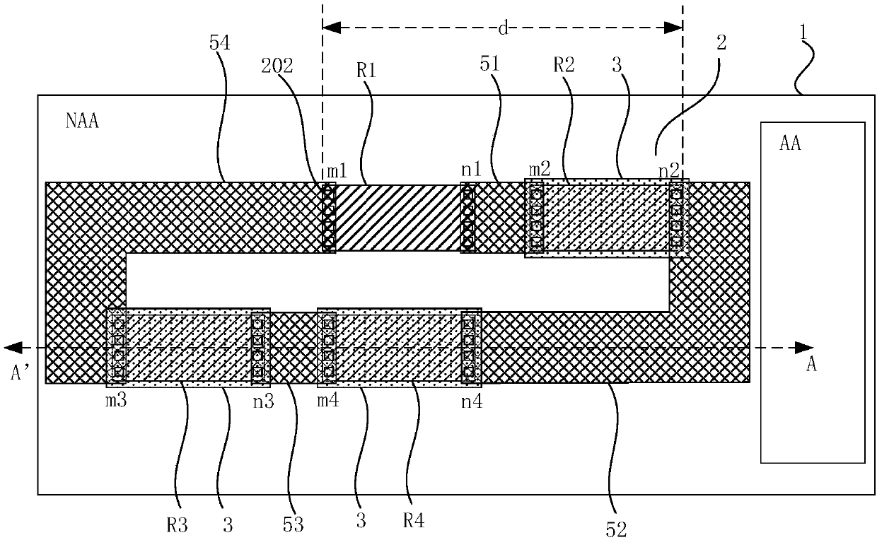
[0028] The present invention will be further described in detail below in conjunction with the accompanying drawings and embodiments. It should be understood that the specific embodiments described herein are only used to explain the present invention, but not to limit the present invention. In addition, it should be noted that, for the convenience of description, the drawings only show some but not all structures related to the present invention. Throughout this specification, the same or similar reference numbers represent the same or similar structures, elements or processes. It should be noted that the embodiments in the present application and the features of the embodiments may be combined with each other in the case of no conflict.

[0029] An embodiment of the present invention provides a display panel, the display panel includes a display area and a non-display area surrounding the display area, a base substrate and at least one bridge structure located on the base s...


PUM


Abstract

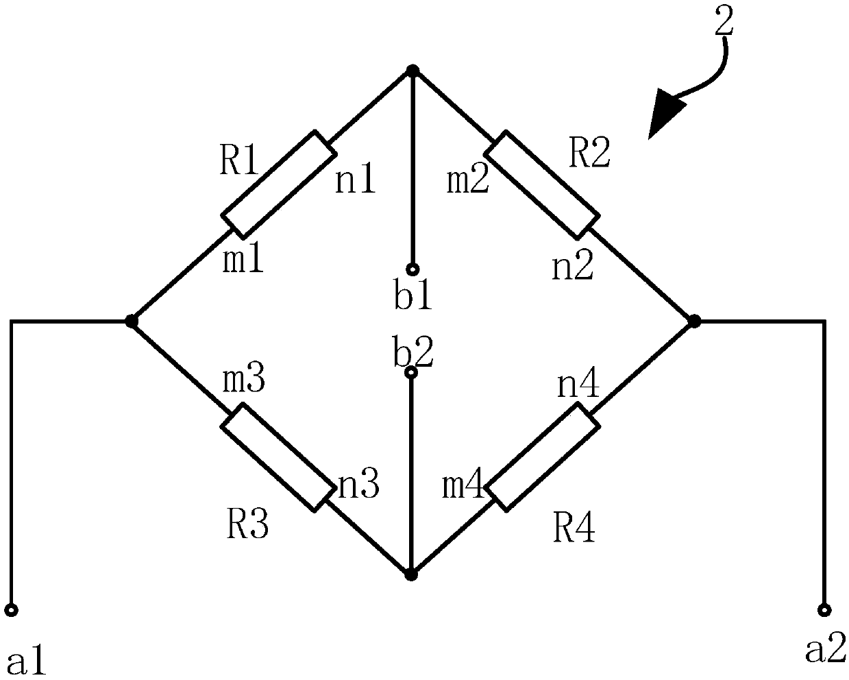
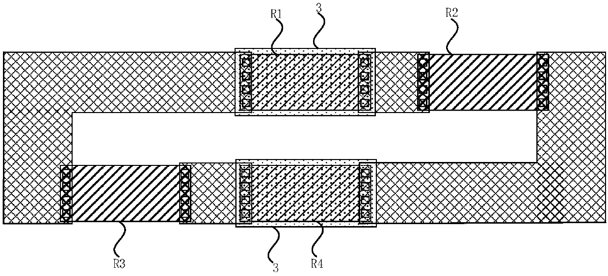
The invention discloses a display panel and a display device. The display panel comprises at least one electric bridge structure, a first light sensation resistor of the electric bridge structure is in series connection between the first voltage signal input end and the first sensing signal output end, a second light sensation resistor of the electric bridge structure is in series connection between the first sensing signal output end and the second voltage signal input end, a third light sensation resistor of the electric bridge structure is in series connection between the first voltage signal input end and the second sensing signal output end, and a fourth light resistor of the electric bridge structure is in series connection between the second sensing signal output end and the secondvoltage signal input end; the ratio of initial resistance values of the first light sensation resistor and the second light sensation resistor is equal to that of initial resistance values of the third light sensation resistor and the fourth light sensation resistor; at least one light sensation resistor in the electric bridge structure is not shielded by a light shielding structure; when the electric bridge structure is effectively illuminated, the ratio of real-time resistance values of the first light sensation resistor and the second light sensation resistor is not equal to that of real-time resistance values of the third light sensation resistor and the fourth light sensation resistor. According to the technical scheme, the influence of temperature on the light sensation detection process is improved while the light sensation detection function of the display panel is enabled.

Description

technical field [0001] Embodiments of the present invention relate to the field of display technology, and in particular, to a display panel and a display device. Background technique [0002] The light intensity of the external environment has a greater impact on the display effect of the display device. For example, when the display device is in a brighter environment, the display screen of the display device is brighter, but when the display device is in a darker environment, the display The display screen of the device may have a ripple phenomenon, and the display screen is too bright, which may easily cause visual fatigue of the user. In addition, if the display screen of the display device is too dark, the color vividness of the display screen of the display device will be greatly reduced. Therefore, the display device is generally provided with a photosensitive structure to detect the brightness of the external environment, and adjust the brightness of the display dev...

Claims


Application Information

Patent Timeline
Patent Type & Authority Applications(China)
IPC IPC(8): G02F1/133
CPCG02F1/13318
Inventor 席克瑞崔婷婷周志伟
Owner WUHAN TIANMA MICRO ELECTRONICS CO LTD
Learn More