Veterinary push-type animal limiting device

A limiting device and propulsion technology, applied in veterinary instruments, animal restraint instruments, medical science, etc., can solve the problems of poor fixation stability and controllability, slow automatic positioning speed for medium and large animals, etc. The effect of achieving fixed stability and controllability is improved, and the effect of accelerating the speed of automatic positioning

Active Publication Date: 2018-03-06
SUSONG XIANGYUAN POULTRY TRADE
View PDF18 Cites 3 Cited by
  • Summary
  • Abstract
  • Description
  • Claims
  • Application Information

AI Technical Summary

Problems solved by technology

[0003] Aiming at the deficiencies in the existing technology, the purpose of the present invention is to provide a veterinary push-type animal restraint device to solve the problem that the existing technology cannot realize the fixation of a suitable size ac

Method used


Image

  • Veterinary push-type animal limiting device
  • Veterinary push-type animal limiting device
  • Veterinary push-type animal limiting device

Examples


Embodiment 1

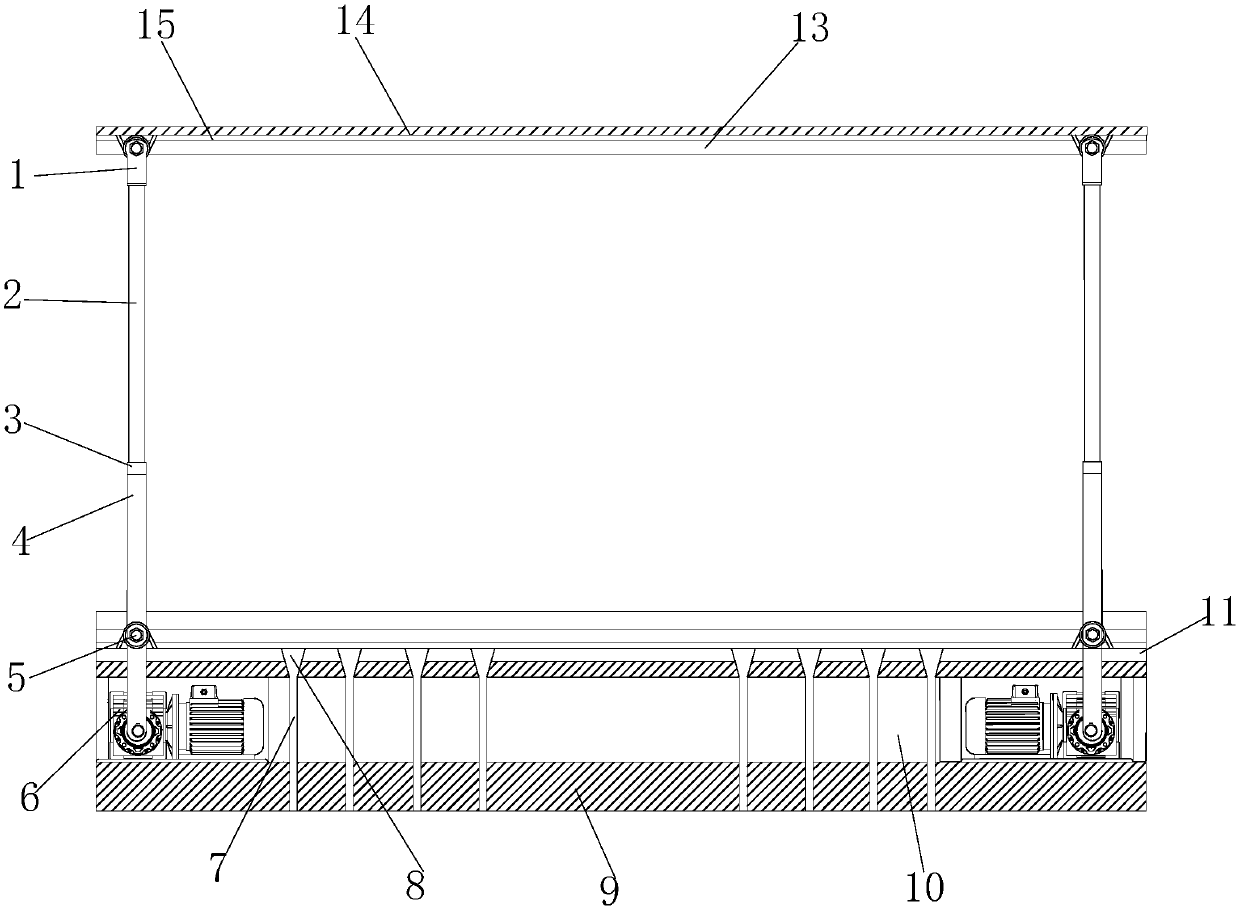
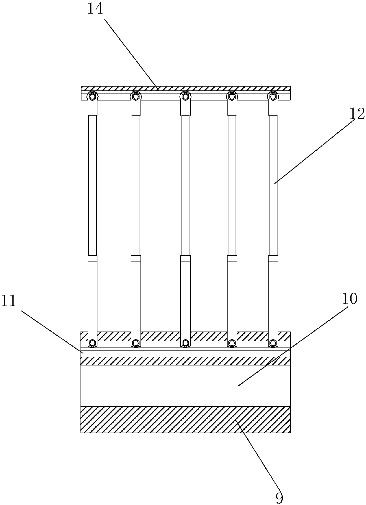
[0032] see Figure 1-Figure 9 , the present invention provides a technical scheme of a veterinary push-type animal restraint device: a veterinary push-type animal restraint device, the structure of which includes an upper moving device 1, a support rod 2, a buffer positioner 3, a hydraulic rod 4, a lower Mobile device 5, drive motor 6, drain pipe 7, water collection port 8, base 9, motor compartment 10, lower guide rail device 11, adjustable support rod 12, heat insulation board 13, anti-seepage board 14, upper guide rail device 15, The upper moving device 1 is installed directly above the support rod 2 and adopts an interference fit, the support rod 2, the buffer positioner 3 and the hydraulic rod 4 are located on the same axis, and the hydraulic rod 4 is provided with a lower Moving device 5, two drive motors 6 are evenly and equally spaced inside the motor compartment 10, and the drive motors 6 are sequentially installed on the same horizontal plane, and the lower guide rai...

Embodiment 2

[0041] see Figure 6 As shown: the lower guide rail device 11 is composed of a water collection tank 1101, a guide rail isolation warehouse 1102, a buffer warehouse 1103, a moving guide rail 1104, and a support warehouse 1105. The water collection tank 1101 and the guide rail isolation warehouse 1102 are welded seamlessly. The bottom of the guide rail isolation warehouse 1102 is provided with a moving guide rail 1104, and a buffer warehouse 1103 is provided between the guide rail isolation warehouse 1102 and the support warehouse 1105, and the bottom of the support warehouse 1105 is welded to the top of the motor warehouse 10.

Embodiment 3

[0042] Example 3: See Figure 5 , Figure 8 , Figure 9 As shown: the hydraulic rod 4 and the hydraulic telescopic rod 55 use hydraulic oil as the driving medium; there are two control methods, that is, the driving part of the external hydraulic power unit is separated from the column or the driving part of the built-in hydraulic unit power unit is placed on the column. The cylinder is driven up and down in the body; the lifting is achieved by locking or releasing the manual key. When the device is in the raised state, after the key is released, it will automatically lock when it is in place, and it will automatically rise after the key is released again. This type of product is mostly used in places where the lifting frequency is not high; the main reason is that the semi-automatic lifting column has low cost, and the second is that the semi-automatic lifting column does not need a control panel, which is easy to operate and simple and direct.


PUM

PropertyMeasurementUnit
Diameteraaaaaaaaaa

Abstract

The invention discloses a veterinary push-type animal limiting device. The veterinary push-type animal limiting device structurally comprises upper movement devices, support rods, buffering locators,hydraulic rods, lower movement devices, driving motors, liquid draining tubes, water collecting openings, a base, a motor cabin, a lower guide rail device, adjustable support rods, a heat-insulating plate, an anti-seepage plate and an upper guide rail device, wherein the upper movement devices are arranged over the support rods in an interference fit way. The lower movement devices are arranged inside the lower guide rail device, the driving motors inside the motor cabin are used for driving the hydraulic rods to realize telescopic deformation, and medium and large-sized animals of different types can be fixed properly in combination with driving connecting rods, torque drivers, hydraulic telescopic rods, first converters and second converters, so that automatic locating speed of the medium and large-sized animals is increased greatly; when certain large animals resist, the fixing stability and controllability are improved greatly.

Description

technical field [0001] The invention is a veterinary push-type animal limiting device, which belongs to the field of veterinary animal fixation devices. Background technique [0002] Large livestock, such as large animals such as cattle, horses, and mules, or medium-sized animals such as pigs and sheep; when diagnosing or treating this type of animal, it needs to be fixed or limited in advance. Fixation means to bind the animal firmly so that the animal cannot directly struggle or move; restraint means to reduce the animal's activity space until it indirectly prevents the animal from moving or struggling. In the prior art, when fixing medium and large animals, most of them adopt the method of binding and fixing the animals, for example, binding the head of the animal to the branch of the trunk, or binding the limbs of the animal to the stake, or binding the Animals are hoisted so that the limbs are suspended in the air, or the animal is picked up by using a net bag; however...

Claims


Application Information

Patent Timeline
IPC IPC(8): A61D3/00
CPCA61D3/00
Inventor 周冰晔
Owner SUSONG XIANGYUAN POULTRY TRADE
Why Eureka
Try Eureka