
Direct-embedded power rod bottom strip split type structure

A power pole split-type technology, applied in the field of direct-buried power pole split structure, can solve the problems of not meeting the actual use requirements, increasing transportation costs, and not being able to disassemble, so as to achieve a reasonable overall structure setting, save transportation space, and facilitate transport effect

Pending Publication Date: 2018-03-06
江苏银河钢杆有限公司
View PDF8 Cites 0 Cited by
  • Summary
  • Abstract
  • Description
  • Claims
  • Application Information

AI Technical Summary

Problems solved by technology

[0002] The bottom cover plate of the existing directly buried power pole is welded and cannot be disassembled during transportation, which occupies a large space and greatly increases the transportation cost, which does not meet the actual use requirements

Method used


Image

  • Direct-embedded power rod bottom strip split type structure
  • Direct-embedded power rod bottom strip split type structure

Examples


Embodiment Construction

[0011] The present invention will be further described below in conjunction with the accompanying drawings and embodiments.

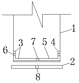
[0012] Such as figure 1 with figure 2 As shown in the present invention, a direct-buried electric power pole bottom bar split structure includes a pole 1 and a bottom cover 2, and a connection is provided in the pole 1 at the junction of the pole 1 and the bottom cover 2. Bar 3, the cross-section of the connecting bar 3 is U-shaped, the connecting bar 3 is composed of a side 4 and a bottom surface 5, and connecting holes are arranged on the side 4 and the bottom surface 5 of the connecting bar 3, which are respectively side connection Holes 6 and bottom connection holes 7, cover plate connection holes 8 are provided on the bottom cover plate 2 corresponding to the bottom connection holes 7, and the rod 1 is composed of an inner rod and an outer rod; the connecting bar 3 and the rod 1 The inner wall is fitted together; the side connecting holes 6 are ...


PUM


Abstract

The invention relates to a direct-embedded power rod bottom strip split type structure comprising a rod and a bottom cover plate. A connecting strip is arranged in the position, at the connecting position of the rod and the bottom cover plate, of the rod, the section of the connecting strip is in a U shape, and the connecting strip is composed of side faces and a bottom face. Connecting holes areformed in the side faces and the bottom face of the connecting strip and are the side connecting holes and the bottom connecting hole correspondingly, a cover plate connecting hole is formed in the position, corresponding to the bottom connecting hole, of the bottom cover plate, and the rod is composed of an inner rod body and an outer rod body. According to the direct-embedded power rod bottom strip split type structure, movable connection is adopted, connecting is firm, and transporting is convenient.

Description

technical field [0001] The invention relates to a direct-buried power pole structure, in particular to a direct-buried power pole split structure. Background technique [0002] The bottom cover plate of the existing directly buried power pole is welded and cannot be disassembled during transportation, which takes up a large space, greatly increases the transportation cost, and does not meet the actual use requirements. Contents of the invention [0003] Purpose of the invention: The purpose of the present invention is to overcome the deficiencies in the prior art and provide a split structure with movable connection, firm connection and convenient transportation for the bottom bar of the directly buried power pole. [0004] Technical solution: In order to solve the above-mentioned technical problems, a direct-buried power pole bottom bar split structure according to the present invention includes a pole and a bottom cover plate, and a A connecting strip, the section of th...

Claims


Application Information

Patent Timeline
IPC IPC(8): E04H12/22
CPCE04H12/2215
Inventor 邵赛军周霖韬
Owner 江苏银河钢杆有限公司
Learn More