Supercharge Your Innovation With Domain-Expert AI Agents!

A hybrid stepper motor with U-shaped permanent magnet embedded in the stator

A stepping motor and permanent magnet technology, applied in the magnetic circuit shape/style/structure, electromechanical devices, electrical components, etc., can solve the problems of low utilization rate of permanent magnets, difficult maintenance and replacement, and high processing difficulty, and achieve the utilization of permanent magnets. The effect of high rate, not easy to demagnetize, and large torque

Active Publication Date: 2020-02-14
JIANGSU DINGS INTELLIGENT CONTROL TECH CO LTD
View PDF7 Cites 0 Cited by
  • Summary
  • Abstract
  • Description
  • Claims
  • Application Information

AI Technical Summary

Problems solved by technology

[0007] In order to solve the defects of high processing difficulty, low utilization rate of permanent magnets, poor heat dissipation and difficult maintenance and replacement existing in the prior art, the present invention provides a hybrid stepper motor with U-shaped permanent magnets embedded in the stator

Method used


Image

  • A hybrid stepper motor with U-shaped permanent magnet embedded in the stator
  • A hybrid stepper motor with U-shaped permanent magnet embedded in the stator
  • A hybrid stepper motor with U-shaped permanent magnet embedded in the stator

Examples


Embodiment Construction

[0024] The present invention will be further described below in conjunction with the accompanying drawings and embodiments.

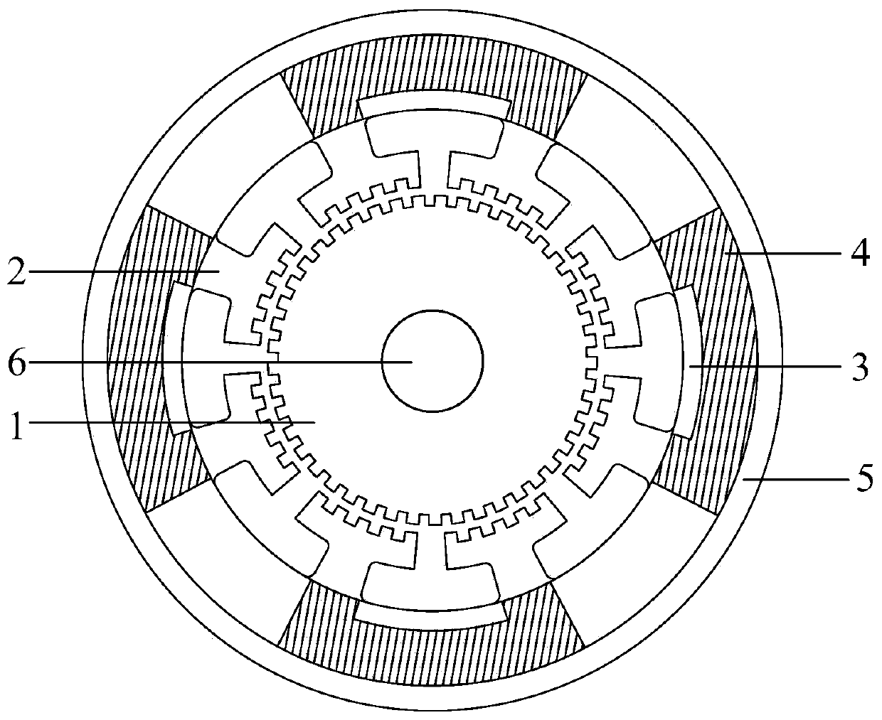
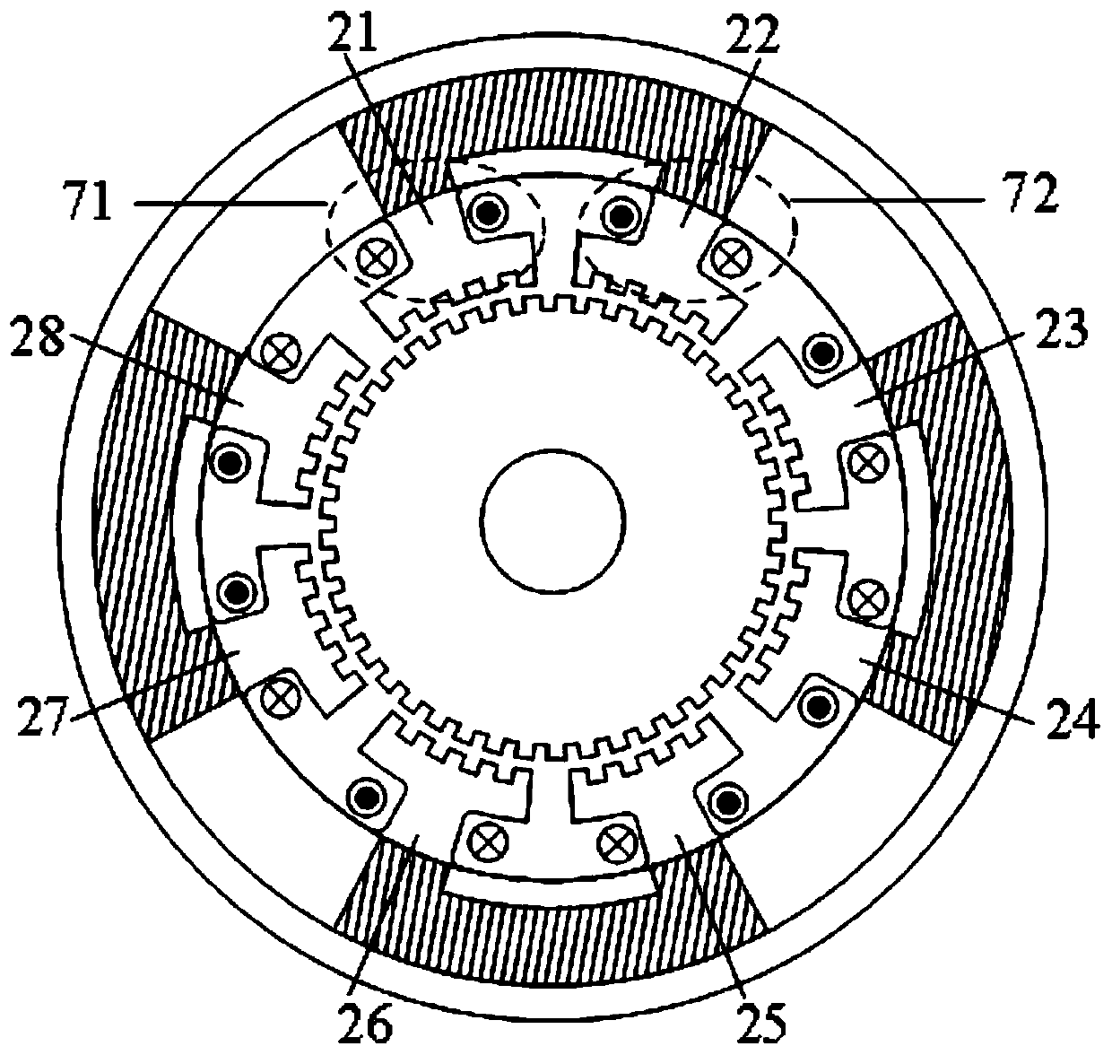
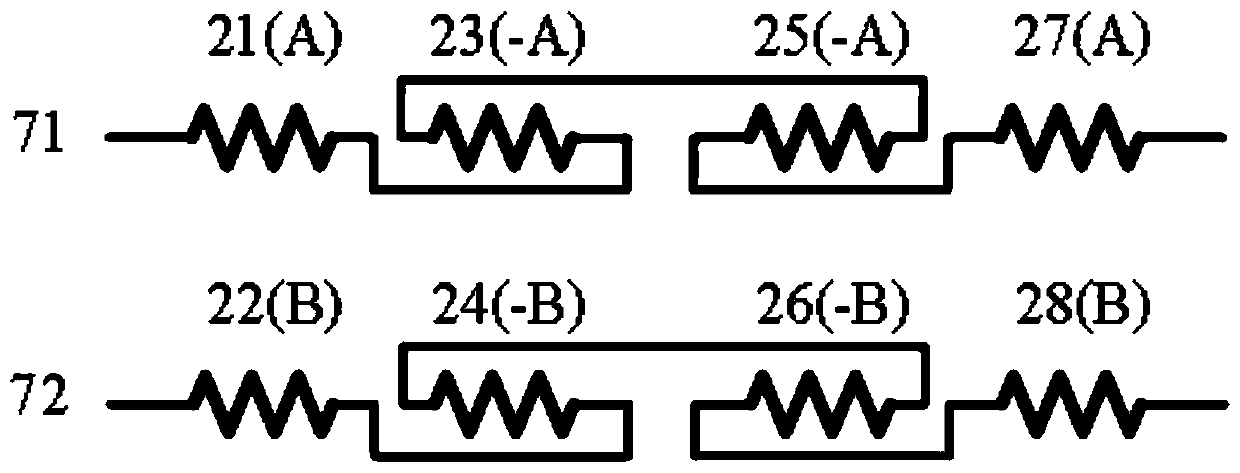
[0025] The present invention is a hybrid stepping motor with a U-shaped permanent magnet embedded in the stator, such as figure 1 and 2 As shown, the stator is composed of stator poles 2, insulation 3, permanent magnets 4, stator coil A-phase winding 71 and stator coil B-phase winding 72. 8 stator poles 2, represented as the first stator pole 21, the second stator pole 22, the third stator pole 23, the fourth stator pole 24, the fifth stator pole 25, the sixth stator pole 26, and the seventh stator pole 27 and the eighth stator pole 28, five small teeth with the same pitch as the rotor teeth are distributed on the pole piece of each stator pole 2, and a phase stator winding is installed on each pole piece of the stator pole 2. The rotor is composed of a laminated rotor core 1 and a rotating shaft 6 inside the core. A non-magnetic casing 5 is sheathed...


PUM


Abstract

The invention discloses a hybrid stepping motor with U-shaped permanent magnets embedded into a stator and belongs to the field of hybrid stepping motors. The hybrid stepping motor comprises a statorand a rotor which are formed by laminating silicon steel sheets, wherein a plurality of rotating teeth are uniformly distributed on the outer circumference of the rotor; the rotor comprises a rotor core and a rotating shaft; the stator comprises a stator core, stator windings, permanent magnets and an insulator; magnetic poles are distributed on the inner circumference of the stator core; five small teeth which are the same as the rotor in tooth pitch are distributed on a pole shoe of each magnetic pole; one phase of stator winding is arranged on the pole shoe of each magnetic pole; permanentmagnet slots are arranged in a yoke of the stator core at intervals of two magnetic poles; the permanent magnets are put into the corresponding permanent magnet slots; N poles and S poles of the permanent magnets are clung to the corresponding magnetic poles separately; and the permanent magnets are alternately arranged in a certain order. The permanent magnets are arranged in the stator core through the U-shaped slots, so that the structure of the rotor is simple, the processing difficulty of the motor is reduced, the hybrid stepping motor is suitable for high-speed operation, good in heat dissipation, not easy to demagnetize and easy to replace, magnetic fields generated by the permanent magnets are radial, and the utilization rate of the permanent magnets is high.

Description

technical field [0001] The invention belongs to the field of hybrid stepping motors, in particular to a hybrid stepping motor with U-shaped permanent magnets embedded in the stator. Background technique [0002] The permanent magnet of the traditional hybrid stepping motor is placed in the middle of the two stacked iron cores on the rotor, and is magnetized through the axial direction, and the small teeth of the two adjacent rotor iron cores need to be staggered by 1 / 2 of the tooth pitch from each other, so there is The following defects: [0003] 1. The structure of the rotor is complex and difficult to process. [0004] 2. Since the permanent magnet is magnetized in the axial direction, but the rotor and the stator are made of laminated silicon steel sheets, there will be a non-magnetic air gap between the adjacent silicon steel sheets, and the magnetic field generated by the stator winding is radial, so The utilization rate of permanent magnets is low. [0005] 3. The ...

Claims


Application Information

Patent Timeline
Patent Type & Authority Patents(China)
IPC IPC(8): H02K37/20H02K1/17
CPCH02K1/17H02K37/20H02K2213/03
Inventor 乔晓华徐毅孙玉霞李华
Owner JIANGSU DINGS INTELLIGENT CONTROL TECH CO LTD
Features
  • R&D
  • Intellectual Property
  • Life Sciences
  • Materials
  • Tech Scout
  • Unparalleled Data Quality
  • Higher Quality Content
  • 60% Fewer Hallucinations
Learn More