Supercharge Your Innovation With Domain-Expert AI Agents!

Urban rail emergency lighting system based on remote monitoring

A technology for emergency lighting and remote monitoring, applied in the field of emergency lighting, can solve the problems of loss of basic attributes of emergency lighting, information distortion, increased labor costs, etc., and achieve the effect of solving remote monitoring problems.

Inactive Publication Date: 2018-03-06
合肥联信电源有限公司
View PDF5 Cites 1 Cited by
  • Summary
  • Abstract
  • Description
  • Claims
  • Application Information

AI Technical Summary

Problems solved by technology

[0002] With the gradual improvement of my country's urban rail system, the emergency lighting system has received more and more attention as a part of urban rail. Based on the actual situation of rail transit, the installation and use environment of emergency power supply is poor, and management personnel cannot obtain the operating status of emergency power supply in real time. , can only pass regular inspections, which increases labor costs on the one hand, and on the other hand, the inspection time is too long, and there will be a power outage for a period of time during the inspection, and the emergency power supply cannot work, which will not only make the emergency lighting lose Its emergency function, and make emergency lighting lose its emergency basic attributes
The traditional communication method is one-to-one communication, which is monotonous and simple, which is not conducive to centralized monitoring, and the transmission distance is short. When long-distance communication is required, it will cause information distortion, which does not meet the requirements of long-distance transmission. Therefore, it needs to be combined with emergency lighting The system establishes a communication system for remote monitoring of emergency power supplies and emergency lamps

Method used


Image

  • Urban rail emergency lighting system based on remote monitoring

Examples


Embodiment Construction

[0019] The following will clearly and completely describe the technical solutions in the embodiments of the present invention with reference to the accompanying drawings in the embodiments of the present invention. Obviously, the described embodiments are only some, not all, embodiments of the present invention. Based on the embodiments of the present invention, all other embodiments obtained by persons of ordinary skill in the art without creative efforts fall within the protection scope of the present invention.

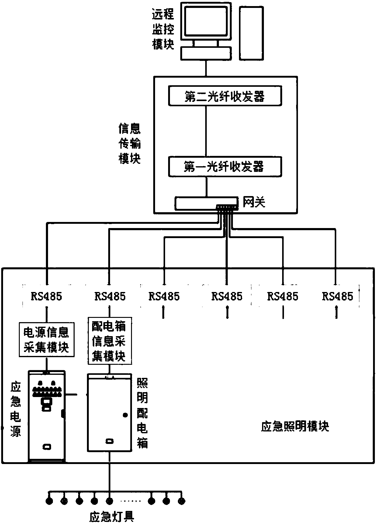
[0020] like figure 1 As shown, the present invention provides an urban track emergency lighting system based on remote monitoring, including an emergency lighting module, an information transmission module and a remote monitoring module. remote monitoring.

[0021] The emergency lighting module includes emergency power supply, power supply information collection unit, lighting distribution box, distribution box information collection unit and RS485 communication i...


PUM


Abstract

The invention discloses an urban rail emergency lighting system based on remote monitoring, which includes an emergency lighting module, an information transmission module and a remote monitoring module. The emergency lighting module is connected with the remote monitoring module through the information transmission module. The emergency lighting module transmits the working state information of an emergency power supply to the information transmission module. The information transmission module realizes remote transmission of the working state information of the emergency power supply throughconversion between a network cable and an optical fiber. The remote monitoring module displays the state information of the emergency power supply, and remotely monitors the emergency lighting module. The urban rail emergency lighting system has the characteristics of being simple and convenient. The problem on how to remotely monitor an emergency lighting system is solved. Inspection by a lot ofmanagement personnel is avoided.

Description

technical field [0001] The invention belongs to the technical field of emergency lighting, and relates to an urban rail emergency lighting system, in particular to an urban rail emergency lighting system based on remote monitoring. Background technique [0002] With the gradual improvement of my country's urban rail system, the emergency lighting system has received more and more attention as a part of urban rail. Based on the actual situation of rail transit, the installation and use environment of emergency power supply is poor, and management personnel cannot obtain the operating status of emergency power supply in real time. , can only pass regular inspections, which increases labor costs on the one hand, and on the other hand, the inspection time is too long, and there will be a power outage for a period of time during the inspection, and the emergency power supply cannot work, which will not only make the emergency lighting lose Its emergency function, and make emergency...

Claims


Application Information

Patent Timeline
Patent Type & Authority Applications(China)
IPC IPC(8): H05B37/02
CPCH05B47/19
Inventor 李多山张力峰
Owner 合肥联信电源有限公司
Features
  • R&D
  • Intellectual Property
  • Life Sciences
  • Materials
  • Tech Scout
  • Unparalleled Data Quality
  • Higher Quality Content
  • 60% Fewer Hallucinations
Learn More