Bottom plate used for suction nozzle or attachment

A technology of bottom plate and accessories, which is applied in the direction of suction nozzle, mechanical device for controlling suction, application, etc., and can solve problems such as damage

Inactive Publication Date: 2018-03-09
福韦尔克股份有限公司
View PDF5 Cites 5 Cited by
  • Summary
  • Abstract
  • Description
  • Claims
  • Application Information

AI Technical Summary

Problems solved by technology

However, this has proven to be disadvantageous: the shell part or the runner against the carpet can cause da...

Method used


Image

  • Bottom plate used for suction nozzle or attachment
  • Bottom plate used for suction nozzle or attachment

Examples


Embodiment approach

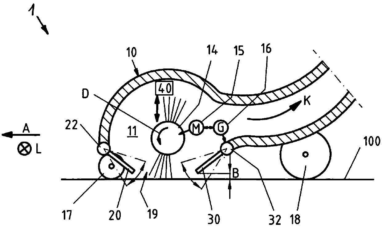
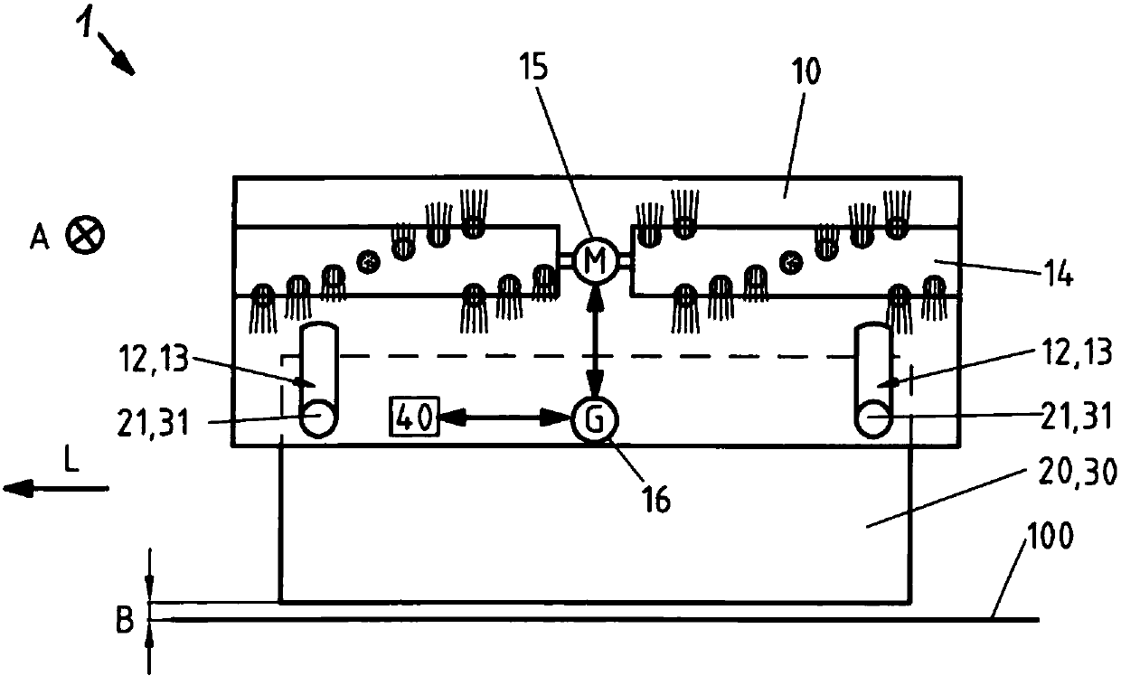
[0040] figure 1 The first embodiment of the present invention is shown. According to this, the front housing part 20 and the rear housing part 30 are each mounted on the housing 10 by means of a joint 22, 32 so as to swing around its longitudinal axis L. Therefore, these housing parts 20, 30 can not only be adjusted in terms of the height of the ground 100, but also can be turned inward into the suction chamber 11 and outwardly out of the suction chamber 11. Therefore, not only the ground distance B of the housing parts 20 and 30 relative to the ground can be adjusted, but also the size of the suction cavity 11 can be adjusted. According to one embodiment, the joints 22, 32 can be constructed in the form of hinge joints, such as film hinge joints. As a result, a swingable movement of the housing parts 20, 30 can be achieved. According to the present invention, the film hinges 22, 32 can be a simple and smart solution to adjustably mount the housing parts 20, 30 on the housing ...


PUM


Abstract

The invention relates to a bottom plate of a suction or attachment of a dust collector or dust collection robot. The bottom plate has a shell (10), a suction cavity (11) for suction of air/dirt particles is formed in the shell, the suction cavity (11) longitudinally extends transverse to a forward direction (A) of the bottom plate (1), the bottom plate also has a rotatable brush (14) arranged in the suction cavity (11) and preferably used for accommodating dirt particles, and the suction cavity (11) is defined by a front shell part (20) and a rear shell part (30). According to the invention, the front shell part (20) and/or the rear shell part (30) is formed in a highly adjustable manner.

Description

Technical field [0001] The present invention relates to a bottom plate for a suction nozzle or accessory of a vacuum cleaner or a cleaning robot, which has a housing, and a suction cavity for sucking in air and / or dirt particles is formed in the housing, wherein the longitudinal extension of the suction cavity Transverse to the forward direction of the bottom plate, the bottom plate also has a rotatable brush arranged in the suction cavity for receiving dirt particles, wherein the suction cavity is defined by the front housing part and the rear housing part. Background technique [0002] Known bottom plates for suction nozzles or accessories of vacuum cleaners or vacuuming robots usually have a housing, or form a part of the housing, in which an elongated suction cavity for sucking in air and / or dirt particles is formed . A rotatable brush is provided in the suction cavity, which can lift from the ground and / or receive dirt particles. The suction cavity downward (or towards the...

Claims


Application Information

Patent Timeline
IPC IPC(8): A47L9/04
CPCA47L9/04A47L9/0072A47L9/0477
Inventor 马库斯·科内利森
Owner 福韦尔克股份有限公司
Why Eureka
Try Eureka