A large-stroke precision flow regulator for transfusion

A technology of flow regulator and large stroke, applied in the field of medical equipment

Active Publication Date: 2020-07-07
玉环市正日科技有限公司
View PDF7 Cites 0 Cited by
  • Summary
  • Abstract
  • Description
  • Claims
  • Application Information

AI Technical Summary

Problems solved by technology

[0016] Aiming at the defects in the above-mentioned prior art, the purpose of the present invention is to solve the above-mentioned problems existing in the existing flow regulator and provide an infusion speed that can realize a large effective stroke, and the liquid medicine does not need to be introduced into the body cavity of the regulator. It is a new precision flow regulator for infusion that adapts to changes in the outer diameter and wall thickness of the infusion tube hose in a wide range, accurate adjustment, convenient installation and operation, only two parts, easy manufacture, and low cost

Method used


Image

  • A large-stroke precision flow regulator for transfusion
  • A large-stroke precision flow regulator for transfusion
  • A large-stroke precision flow regulator for transfusion

Examples


Embodiment Construction

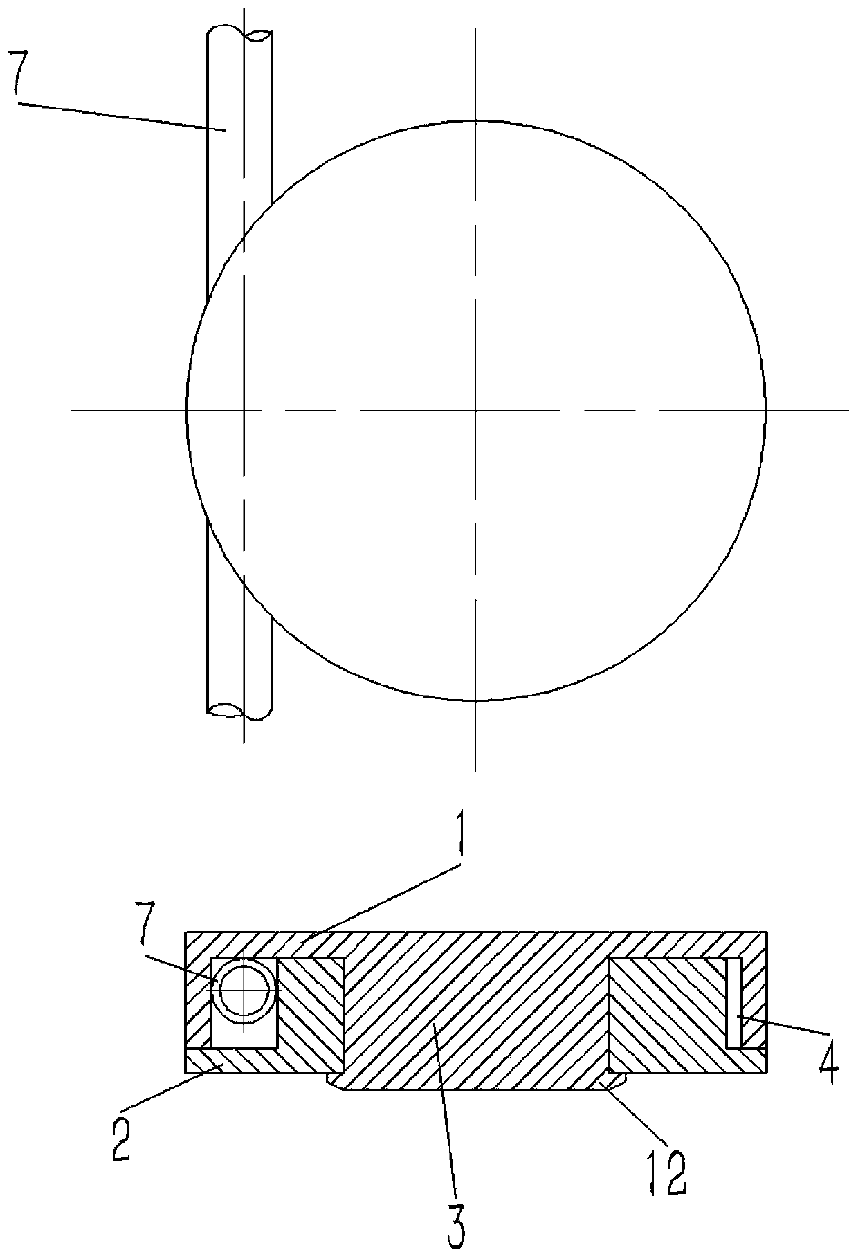
[0040] The present invention will be further described below with specific embodiment, as Figure 1-6 shown.

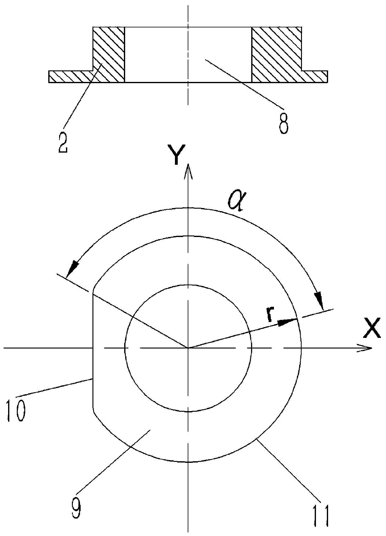
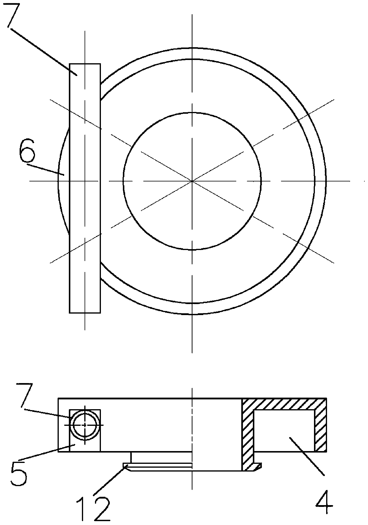
[0041] A large-stroke precision flow regulator for infusion, including a housing 1 and an adjustment wheel 2 for adjusting the infusion speed. The adjustment wheel 2 adjusts the size of the cross-sectional area by squeezing the hose 7 to achieve the adjustment function. There is a center of the housing 1. The shaft cylinder 3 is provided with an annular cavity 4 between the outer cylindrical surface of the casing 1 and the shaft cylinder 3. The annular cavity 4 and the shaft cylinder 3 are at the same axis, and a hose support plate 6 is arranged on the casing 1. The soft Both sides of the tube support plate 6 are provided with hose holes 5; part of the hose 7 is installed inside the annular cavity 4 through the hose holes 5, and the adjustment wheel 2 is provided with a shaft hole 8 that is compatible with the shaft cylinder 3. The center of the wheel 2 is provided w...


PUM


Abstract

The invention belongs to the technical field of medical instruments and relates to a flow regulator, in particular to a large-travel precise flow regulator for infusion. The flow regulator comprises acasing and an adjusting wheel for adjusting the infusion speed, wherein a shaft cylinder is arranged in the center of the casing, an annular cavity concentric with the shaft cylinder is arranged between the outer cylindrical surface of the casing and the shaft cylinder, a hose support plate is arranged on the casing, and hose holes are formed in two sides of the hose support plate; a shaft hole matched with the shaft cylinder is formed in the adjusting wheel; a hose pressing element is arranged at the center of the adjusting wheel, the center line of the hose pressing element overlaps with the center line of the adjusting wheel, and the outer side surface of the hose pressing element comprises a plane and a cylindrical surface. The flow regulator is high in adjusting precision and long ineffective adjusting travel, infusion liquid medicine is not needed to be introduced into a cavity of the regulator, adhesion is not required when the flow regulator is mounted on infusion apparatus,the flow regulator comprises two parts, and a seal structure is not needed to be considered, so that the flow regulator is simple in structure and low in cost.

Description

technical field [0001] The invention belongs to the technical field of medical devices, and relates to a flow regulator, in particular to a large-stroke precision flow regulator for infusion. Background technique [0002] The clinically used infusion set is currently the most used flow regulator of a linear guide roller type, which uses the roller to compress the infusion set hose to produce a change in cross-sectional area to achieve infusion speed adjustment. It consists of a roller and an infusion tube groove. The bottom plate of the infusion tube groove and the roller guide rail groove are all linear, and there is an angle between them. When the roller moves along the guide rail groove, the distance between the bottom of the roller and the bottom of the infusion tube groove will change. Change. At this time, the cross-section of the infusion hose worn in the infusion tube tank will be compressed by the roller, resulting in a change in the cross-sectional area of ​​the h...

Claims


Application Information

Patent Timeline
Patent Type & Authority Patents(China)
IPC IPC(8): A61M5/175
CPCA61M5/16881
Inventor 唐增基郏正秋
Owner 玉环市正日科技有限公司
Why Eureka
Try Eureka