Supercharge Your Innovation With Domain-Expert AI Agents!

Clamping control device

A control device and clamping plate technology, applied in workpiece clamping devices, manufacturing tools, etc., can solve the problems of waste of optical cables, clamping control devices without optical cable cutting and clamping, complicated clamping operations, etc., and achieve an increase in length value. Effect

Active Publication Date: 2018-03-09
中通服供应链管理有限公司
View PDF5 Cites 5 Cited by
  • Summary
  • Abstract
  • Description
  • Claims
  • Application Information

AI Technical Summary

Problems solved by technology

Existing optical cables will be cut into optical cables of different lengths according to needs. If the optical cable after cutting is too long, it will cause waste of optical cable. If the optical cable after cutting is too short, it will not meet the needs. Therefore, the cable needs to be cut when cutting. Clamping and fixing to improve cutting accuracy, but the existing clamping control mechanisms are various, and the clamping operation is complicated, and there is no clamping control device specially used for clamping optical cable cutting. Therefore, we propose a Clamping control device to improve the cutting accuracy of fiber optic cable

Method used


Image

  • Clamping control device
  • Clamping control device
  • Clamping control device

Examples


Embodiment 1

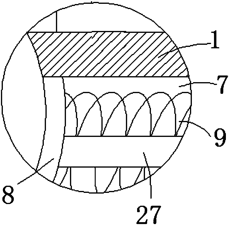
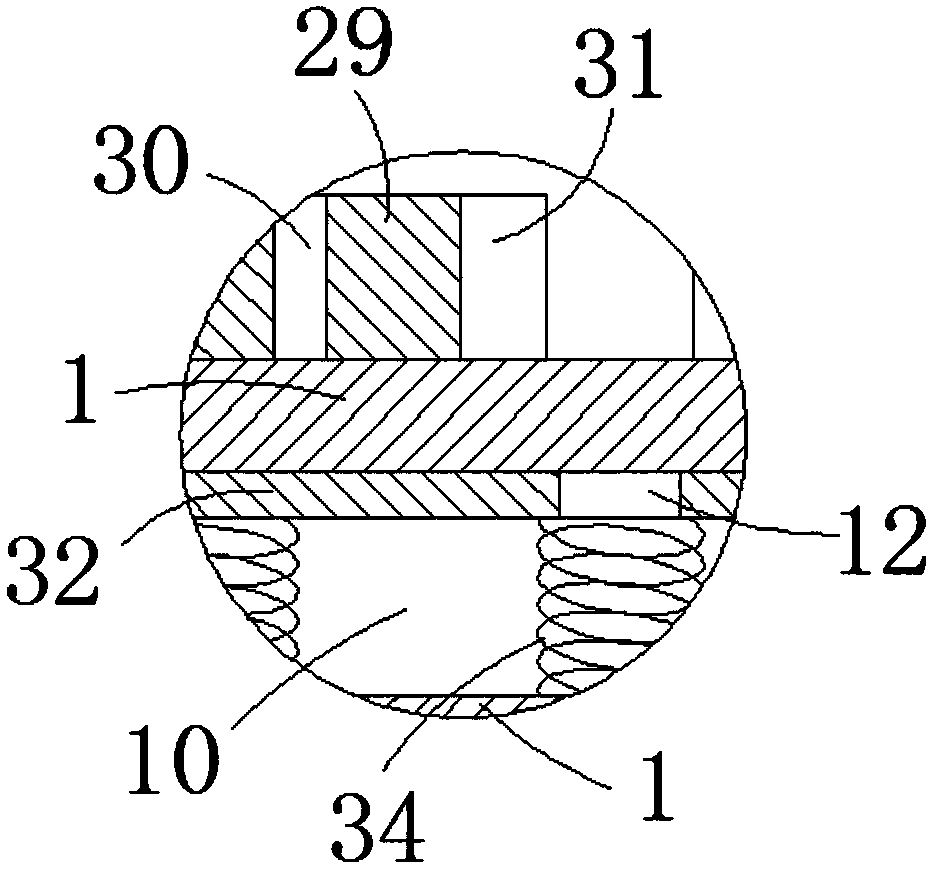
[0018] Such as Figure 1-3 As shown, a clamping control device includes a base plate (1), a housing groove (7) is provided in the base plate (1), and two arc-shaped clamping plates ( 8), the side wall of the arc-shaped clamping plate (8) is fixedly connected with the first spring (9), which is convenient for the two arc-shaped clamping plates 8 to clamp the cable, and the first spring (9) The other end is fixedly connected to the side wall of the receiving groove (7), and the side wall of the arc-shaped clamping plate (8) is fixedly connected with a moving mechanism to facilitate the movement of the arc-shaped clamping plate 8. The bottom plate (1 ) is provided with an accommodating chamber (10) inside, and the accommodating chamber (10) is provided with a control mechanism.

[0019] Wherein, the moving mechanism includes a moving rod (27), one side wall of the arc-shaped clamping plate (8) is fixedly connected with the moving rod (27), and one end of the moving rod (27) is f...

Embodiment 2

[0022] Such as figure 2 and Figure 4-7 As shown, the application of a clamping control device in a rapid optical cable tester specifically includes a base plate 1, one end of the base plate 1 is rotatably connected to a cover plate 2, and one end surface of the base plate 1 is provided with a limit groove 3, the limit groove Scale lines 4 are evenly distributed on the side wall of 3, which is convenient for measuring the length of the cable. The upper side of the limit groove 3 is provided with two connecting plates 5. Specifically, the upper side of the connecting plate 5 is provided with a plurality of fastening bolts. 26. The connecting plate 5 is provided with a first bolt hole, and the bottom plate 1 is provided with a second bolt hole. One end of the fastening bolt 26 passes through the first bolt hole and the second bolt hole to fix the connecting plate 5 on the bottom plate 1. On the side wall, it is convenient to install and disassemble the connecting plate 5, two ...


PUM


Abstract

The invention relates to the field of clamping devices, in particular to a clamping control device which can quickly clamp clamping plates for fixing optical cables. The clamping control device comprises a bottom plate, wherein an accommodating groove is formed in the bottom plate, two arc-shaped clamping plates are glidingly connected in the accommodating groove, a first spring is fixedly connected with one side wall of each arc-shaped clamping plate, the other end of each first spring is fixedly connected to the side wall of the accommodating groove, a moving mechanism is fixedly connected with one side wall of each arc-shaped clamping plate, an accommodating cavity is formed in the inner side of the bottom plate, and a control mechanism is arranged in the accommodating cavity. The clamping control device has the advantages as follows: the state of the arc-shaped clamping plates can be controlled conveniently by the aid of the control mechanism arranged in the bottom plate, so that cables are quickly clamped, and the lengths of cut cables are increased.

Description

technical field [0001] The invention relates to the field of clamping devices, in particular to a clamping control device capable of quickly clamping a clamping plate for fixing an optical cable. Background technique [0002] Clamping devices are currently used in many fields, such as machinery, woodworking, etc., and different shapes of clamping devices can be suitable for different purposes. Existing optical cables will be cut into optical cables of different lengths according to needs. If the optical cable after cutting is too long, it will cause waste of optical cable. If the optical cable after cutting is too short, it will not meet the needs. Therefore, the cable needs to be cut when cutting. Clamping and fixing to improve cutting accuracy, but the existing clamping control mechanisms are various, and the clamping operation is complicated, and there is no clamping control device specially used for clamping optical cable cutting. Therefore, we propose a Clamping contro...

Claims


Application Information

Patent Timeline
IPC IPC(8): B21F11/00B25B11/00
Inventor 陆军陈礼晨姚磊
Owner 中通服供应链管理有限公司
Features
  • R&D
  • Intellectual Property
  • Life Sciences
  • Materials
  • Tech Scout
  • Unparalleled Data Quality
  • Higher Quality Content
  • 60% Fewer Hallucinations
Learn More