Surface texturing method for improving wear resistance of guiding rails of sand core moulding machine
A surface texture and molding machine technology, which is applied to the parts of molding machines, casting molding equipment, manufacturing tools, etc., can solve the problems of poor wear resistance of guide rails, achieve the effects of reducing friction coefficient, reducing the number of sand particles, and reducing wear
- Summary
- Abstract
- Description
- Claims
- Application Information
AI Technical Summary
Problems solved by technology
Method used
Image
Examples
Embodiment 1
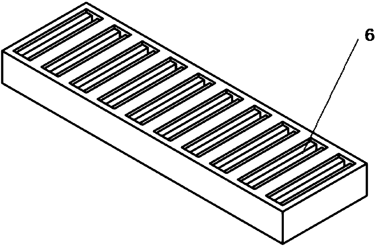
[0031]The present invention is a surface texturing method for improving the wear resistance of the guide rail of a sand core molding machine. The two-layer groove-type texture structure is processed by micro-milling, and the texture appearance is as follows: figure 2 , image 3 As shown, the texture parameters are as follows: the groove depth h of the first layer of groove 1 1 =0.02mm, total groove depth h 2 =0.42mm; first layer groove width w 1 =1.50mm; the groove width w of the second layer of groove 2 2 = 1.00mm; groove spacing s = 3.05mm, the surface of the guide rail 3 to be processed is firstly finished, so that the surface roughness Ra of the guide rail is about 0.10 μm, after the surface of the guide rail 3 is finished, the diameter is passed through the high-speed micro-milling machine The micro milling cutter is used to process the groove texture. First, the first layer of groove 1 is processed. After the tool setting is completed, the milling cutter rotates at ...
Embodiment 2
[0033] The two-layer pit-type texture structure is processed by micro-milling, and the texture appearance is as follows Figure 4 , Figure 5 shown. The texture parameters are as follows: the pit depth h of the pit 4 of the first layer 3 =0.02mm, the total depth of pits h 4 =0.42mm; the first layer pit diameter d 1 =Φ1.50mm, the diameter d of the pit 5 on the second layer 2 =Φ1.00mm; X-direction and Y-direction spacing s 1 =s 2 = 3.05 mm. First, the surface of the guide rail 3 to be processed is finished, so that the surface roughness Ra of the guide rail is about 0.10 μm. Machining the pit 4 of the first layer: After the tool setting, the milling cutter with a diameter of Φ1mm rotates at a high speed of 40000r / min at a high speed of 0.50mm / s and descends 0.12mm relative to the surface of the guide rail along the Z negative direction at a feed speed of 0.50mm / s, and then mills The knife takes the current tool axis as the center of rotation, and mills the first la...
PUM
| Property | Measurement | Unit |
|---|---|---|
| Surface roughness | aaaaa | aaaaa |
| Surface roughness | aaaaa | aaaaa |
| Surface roughness | aaaaa | aaaaa |
Abstract
Description
Claims
Application Information
 - R&D
- Intellectual Property
- Life Sciences
- Materials
- Tech Scout
- Unparalleled Data Quality
- Higher Quality Content
- 60% Fewer Hallucinations
Browse by: Latest US Patents, China's latest patents, Technical Efficacy Thesaurus, Application Domain, Technology Topic, Popular Technical Reports.
© 2025 PatSnap. All rights reserved.Legal|Privacy policy|Modern Slavery Act Transparency Statement|Sitemap|About US| Contact US: help@patsnap.com


