
Simple trash remover for trash rack

A technology of a trash rack and a trash cleaning machine, which is applied to the cleaning of open water surfaces, water conservancy projects, construction, etc., can solve the problems of inconvenient use, inconvenient maintenance, and high manufacturing costs, and achieve convenient use, simple structure, and low manufacturing costs. Effect

Pending Publication Date: 2018-03-09
NEIJIANG DONGGONG HYDROPOWER EQUIP MFR
View PDF4 Cites 6 Cited by
  • Summary
  • Abstract
  • Description
  • Claims
  • Application Information

AI Technical Summary

Problems solved by technology

The hydraulic cleaning machine has the advantages of flexible use, but the structure is slightly complicated, the manufacturing cost is high, and a hydraulic station is required, which is inconvenient for later maintenance; Movement), the remaining dirt in the river, such as branches, weeds, etc., will gather in front of the trash rack again due to the turbulent flow when the cleaning bucket rises. When the dirt in the cleaning bucket is cleaned up, the bucket will go up When preparing for the next cleaning, due to the obstruction of branches and weeds in the river, it is difficult for the cleaning rake bucket to drop to the bottom of the river (that is, the bottom of the trash rack) by its own gravity. At this time, clean again Sometimes it is often necessary to manually salvage part of the sundries so that the cleaning bucket can be smoothly lowered to the bottom of the river
It can be seen that the cleaning machine in the prior art also has the disadvantage of inconvenient use, and it is necessary to improve

Method used


Image

  • Simple trash remover for trash rack
  • Simple trash remover for trash rack
  • Simple trash remover for trash rack

Examples


Embodiment Construction

[0020] Embodiments of the invention are described in detail below, but the invention can be practiced in many different ways as defined and covered by the claims.

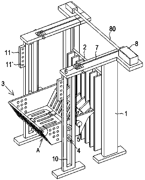
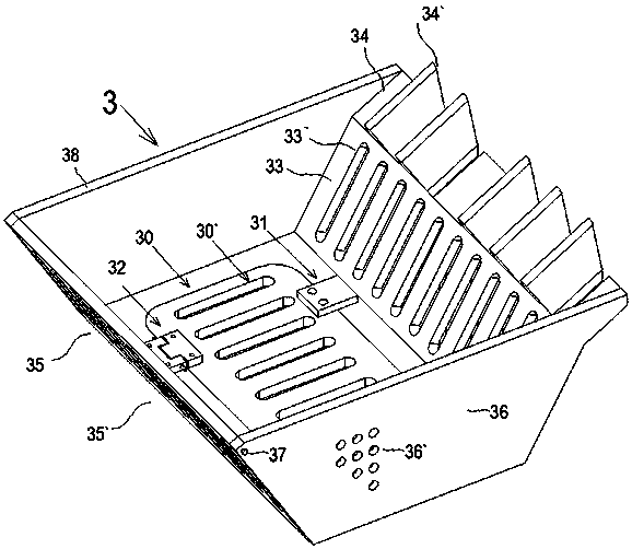
[0021] see figure 1 , the present invention provides 1 a kind of simple cleaning machine that is used for trash rack, comprises frame 1, and the rear side of described frame 1 is provided with trash rack 2, and the front side is slidably provided with the cleaning machine that can lift up and down. The rake bucket 3 is provided with a driving device for driving the cleaning rake bucket 3 up and down. The cleaning rake bucket 3 is an inverted trapezoidal box with an open upper side, and a hole is provided in the lower part of the hole, and a movable The overturned flap 30; the right waist plate 33 of the cleaning rake bucket 3 near the side of the trash rack 2 is provided with a rake tooth part 34 that is integrally formed and forms an angle of 120° with the right waist plate 33. The rake tooth part 34 is provided ...


PUM


Abstract

The invention discloses a simple trash remover for a trash rack. The simple trash remover comprises a machine frame, the trash rack, a trash removing scraper shovel and a driving device, wherein the trash removing scraper shovel is a reverse trapezoidal box body with the open upper side; a hole is formed in the lower part; a turning plate capable of turning is arranged on the hole; an integrally formed harrow tooth part forming an included angle being 120 degrees with a right waist plate is arranged on the right waist plate at one side, near the trash rack, of the trash removing scraper shovel; a triangular cone is arranged on the harrow tooth part; the bottom end of the left waist plate of the trash removing scraper shovel is hinged onto a bottom plate of the trash removing scraper shovelthrough a hinge; the upper end of the left waist plate is tightly locked and fixed onto the adjacent front and back waist plates through a pin; a plurality of penetrating first insertion pin holes are formed in the front and back waist plates; a scraper shovel frame is arranged at the front side of the machine frame; a long groove in which a scraper shovel rolling wheel rolls is formed in the scraper shovel frame. The turning plate capable of turning is designed at the bottom of the trash removing scraper shovel, so that the entering of the trash in the next time after the former trash removal can be convenient; the structure is simple; the manufacturing cost is low; the trash removal efficiency is high; the use is convenient.

Description

technical field [0001] The invention mainly relates to the cleaning equipment of the trash rack of the water inlet of the water turbine of the power station or the water diversion port of the pumping station. Background technique [0002] Trash racks are generally installed at the water inlet of hydro turbines in power stations or water diversions of pump stations to intercept dirt in the water to prevent the dirt from endangering the safe operation of turbines or pump stations. The dirt attached to the surface of the trash rack and the dirt accumulated in front of the trash rack are generally removed by cleaning equipment, so as to prevent these dirt from causing head loss and endangering the safety of the trash rack. [0003] In the prior art, a hydraulic cleaning machine is generally used to clean up the dirt attached to the surface of the trash rack, which includes a bucket frame and a bucket connected to the bucket frame, and a guide wheel is provided under the bucket f...

Claims


Application Information

Patent Timeline
IPC IPC(8): E02B15/10E02B15/06
CPCE02B15/06E02B15/10
Inventor 龚润清刘默浪范灏兰钟旭王秉卓温鹏高
Owner NEIJIANG DONGGONG HYDROPOWER EQUIP MFR
Learn More