A manhole cleaning device

A technology for inspection wells and connecting devices, which is applied in water supply devices, waterway systems, buildings, etc., can solve the problems of not achieving the expected effect, low cleaning efficiency, single function, etc., to increase the range of suction, improve the efficiency of suction, Good cleaning effect

Active Publication Date: 2019-11-05
江苏英斯坦福环境科技有限公司
View PDF8 Cites 0 Cited by
  • Summary
  • Abstract
  • Description
  • Claims
  • Application Information

AI Technical Summary

Problems solved by technology

This cleaning method of inspection well sludge and sand is not only time-consuming and laborious, but also has low operating efficiency. More importantly, the sludge and sand left on the job site and the foul smell emitted by vehicles during transportation seriously pollute the environment.
The general inspection well cleaning device has a single function, low cleaning efficiency, and the cleaning effect is poor, and the expected effect cannot be achieved.

Method used


Image

  • A manhole cleaning device
  • A manhole cleaning device
  • A manhole cleaning device

Examples


Embodiment Construction

[0018] The following will clearly and completely describe the technical solutions in the embodiments of the present invention with reference to the accompanying drawings in the embodiments of the present invention. Obviously, the described embodiments are only some, not all, embodiments of the present invention. Based on the embodiments of the present invention, all other embodiments obtained by persons of ordinary skill in the art without making creative efforts belong to the protection scope of the present invention.

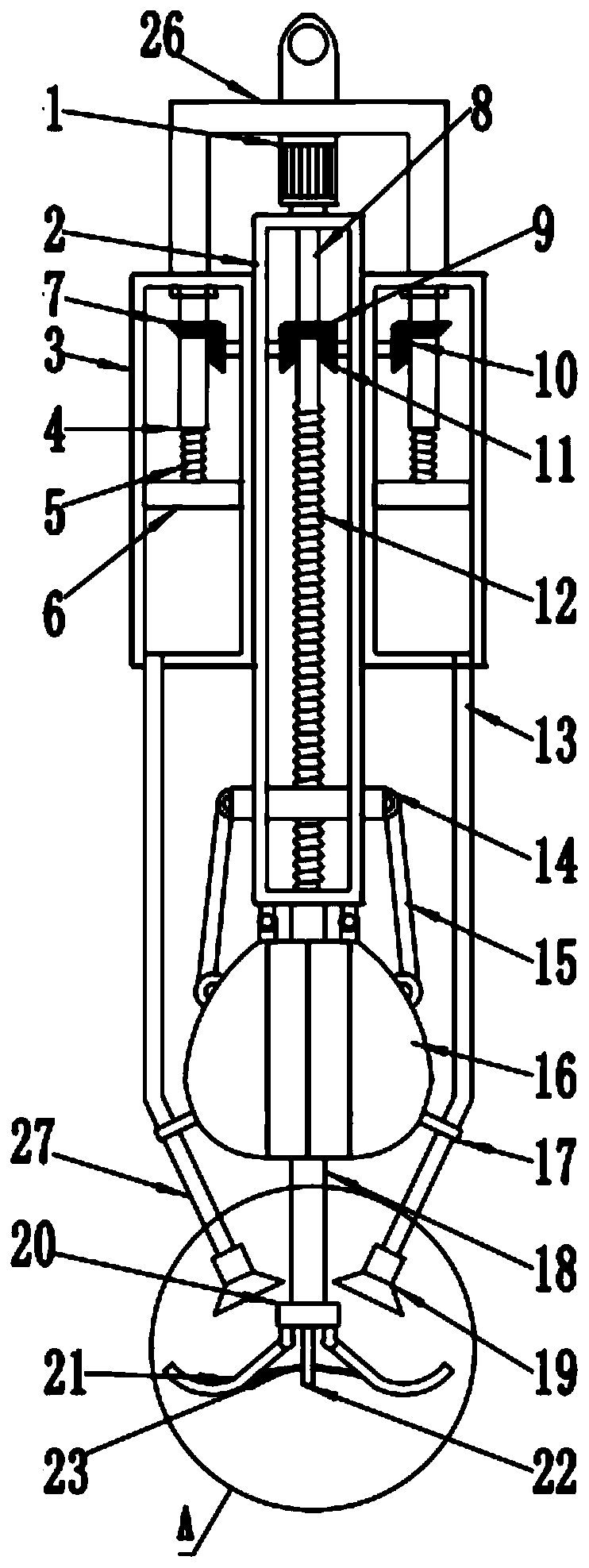
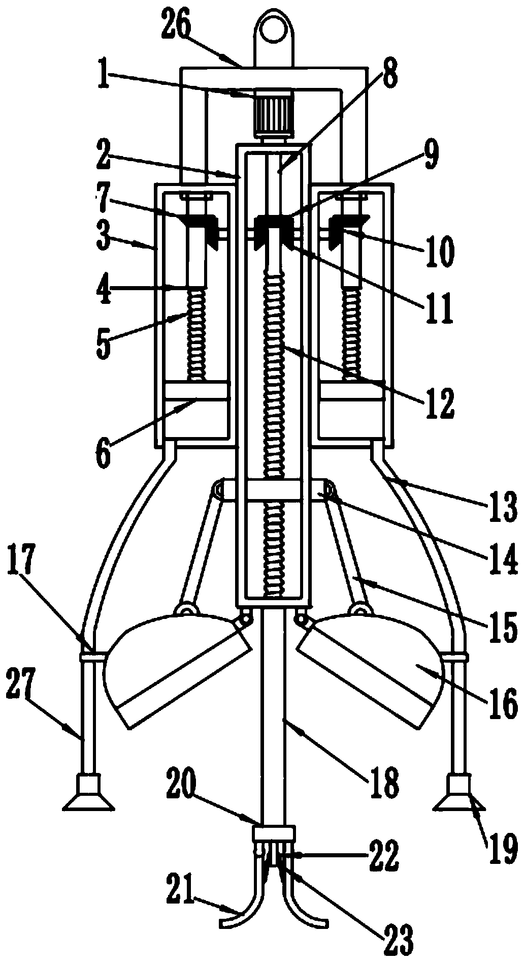
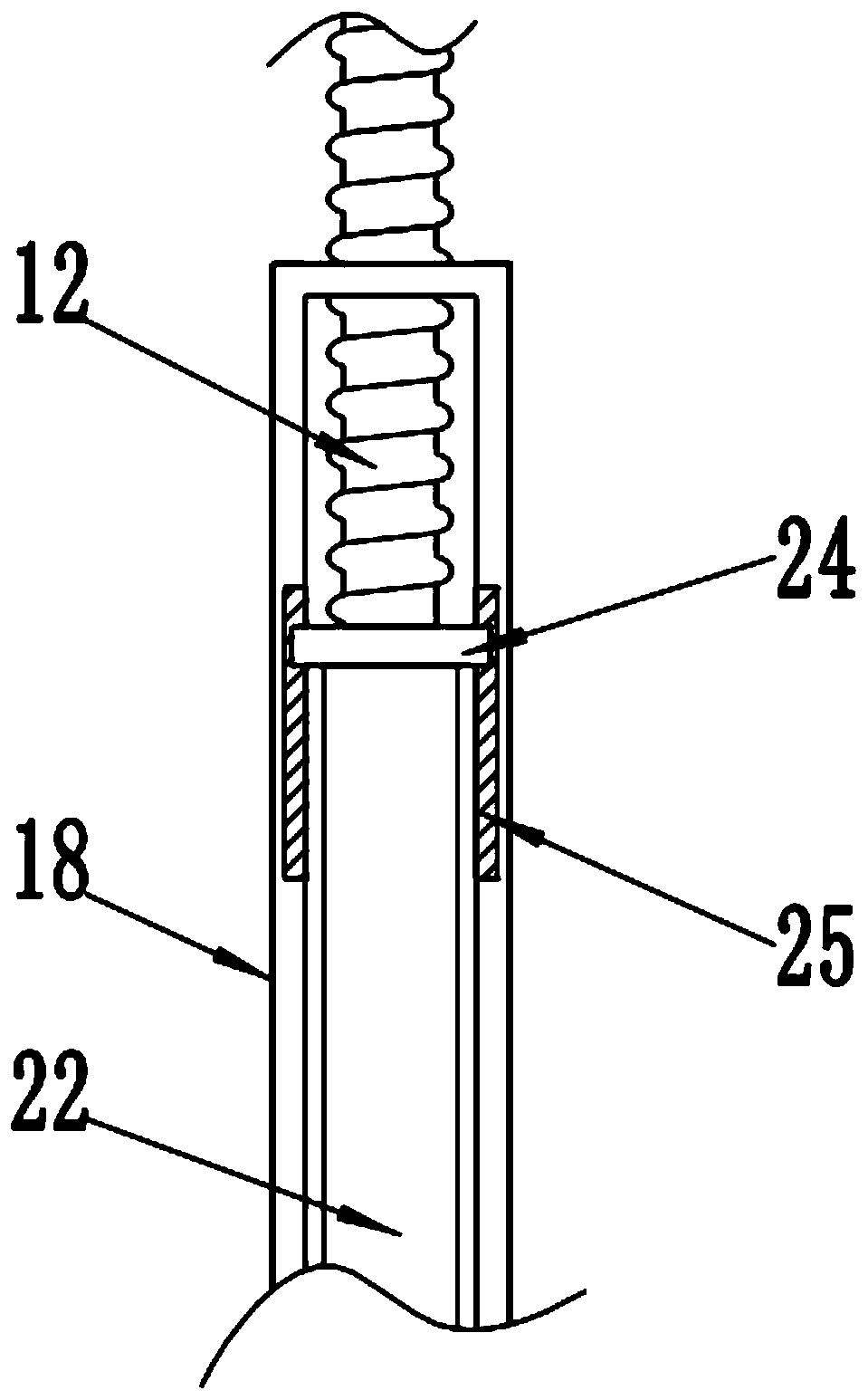
[0019] see Figure 1-4 , a manhole cleaning device, comprising a connecting device 26, a forward and reverse motor 1, a transmission groove 2, a suction chamber 3, a cleaning bucket 16 and an arc-shaped claw bucket 21; Motor 1, the forward and reverse motor 1 is fixedly connected with the rotating shaft 8, the rotating shaft 8 runs through the upper end of the transmission groove 2 and is fixedly connected with the threaded rod B12, when the forward and revers...


PUM


Abstract

The invention discloses a manhole trash cleaning device. The manhole trash cleaning device comprises a connecting device, a forward-reverse motor, a driving groove, a trash suction groove, trash cleaning hoppers and arc grippers, wherein the forward-reverse motor is arranged above the driving groove and fixedly connected with a rotary shaft, and the rotary shaft penetrates the upper end of the driving groove and is fixedly connected with a threaded rod B; trash suction cavities are symmetrically connected to the left and right ends of the driving groove; a moving block is in threaded connection onto the threaded rod B; the trash cleaning hoppers are symmetrically hinged to the lower end of the driving groove; a cylindrical tube is fixedly connected to the center of the lower end of the driving groove; a moving sleeve is sleeved with a ring which is fixedly connected with the moving sleeve; a fixed block is fixedly mounted at the lower end of the cylindrical tube, and the arc grippers are symmetrically hinged to the lower end of the fixed block. The manhole trash cleaning device is simple in structure and convenient to operate, trash on the surface of sewage in a manhole can be cleaned, sludge in the manhole can be cleaned simultaneously, the cleaning efficiency is high, and the trash cleaning effect is good.

Description

technical field [0001] The invention relates to a decontamination device, in particular to a decontamination device for a manhole. Background technique [0002] The inspection well is used in the turning, branching, falling, etc. of the drainage pipes to facilitate inspection and dredging. The scientific name is the inspection well. In the same way, inspection wells for telecommunication cables and power cable inspection wells buried underground are also called inspection wells. Manhole means basement. [0003] At present, most of the cleaning operations of sludge and sand in urban inspection wells are done manually, by manually digging out the sludge and sand from the inspection well, and then transporting the sludge and sand away by vehicles. The cleaning method of this inspection shaft sludge is not only time-consuming and laborious, but also has low operating efficiency, and more importantly, the sludge and sand left over from the operation site and the foul smell give...

Claims


Application Information

Patent Timeline
Patent Type & Authority Patents(China)
IPC IPC(8): E03F7/00
CPCE03F7/00
Inventor 朱灏欣汤沛东
Owner 江苏英斯坦福环境科技有限公司
Why Eureka
Try Eureka