Parallel stage separation free flight wind tunnel testing device with mass center located on interface

A technology of inter-stage separation and wind tunnel testing, which can be used in measurement devices, aerodynamic testing, and testing of machine/structural components. , to achieve the effect of ensuring reliability

Active Publication Date: 2018-03-09
CHINA ACAD OF AEROSPACE AERODYNAMICS
View PDF5 Cites 11 Cited by
  • Summary
  • Abstract
  • Description
  • Claims
  • Application Information

AI Technical Summary

Problems solved by technology

In the past, the axis of the separation force of the separation mechanism must pass through the center of mass of the model to prevent the separation action from affecting the attitude angle of the model. However, for the free-flying wind tunnel test of parallel interstage separation with the center of mass located at the interface, the separation mechanism is arranged in the area of ​​the center of mass It will inevitably destroy the shape of the model, and the shape of the damage is firmly not allowed in the wind tunnel test, so the previous test plan must be improved
[0004] Furthermore, the contact surface of the original upper and lower model fixing nails adopts a "convex" and "concave" design, which is simple in design and can prevent the mutual rotation of the fixing nail and the two models when a pin shaft is used, and this form of fixing nail has a The fatal flaw is that when the pin is pulled out, the constraint of the "convex" fixed pin must be released first, and then the constraint of the "concave" fixed pin must be released. Therefore, the model corresponding to the "convex" pin must first obtain six degrees of freedom. However, six degrees of freedom are obtained after using the model corresponding to the "concave" fixed nail, which is inconsistent with the real hope that the upper and lower models can obtain degrees of freedom at the same time, and will inevitably reduce the credibility of the test results.
Therefore, previous test techniques must be improved

Method used


Image

  • Parallel stage separation free flight wind tunnel testing device with mass center located on interface
  • Parallel stage separation free flight wind tunnel testing device with mass center located on interface
  • Parallel stage separation free flight wind tunnel testing device with mass center located on interface

Examples


Embodiment Construction

[0026] The present invention will be further described in detail below in conjunction with the accompanying drawings, so that those skilled in the art can implement it with reference to the description.

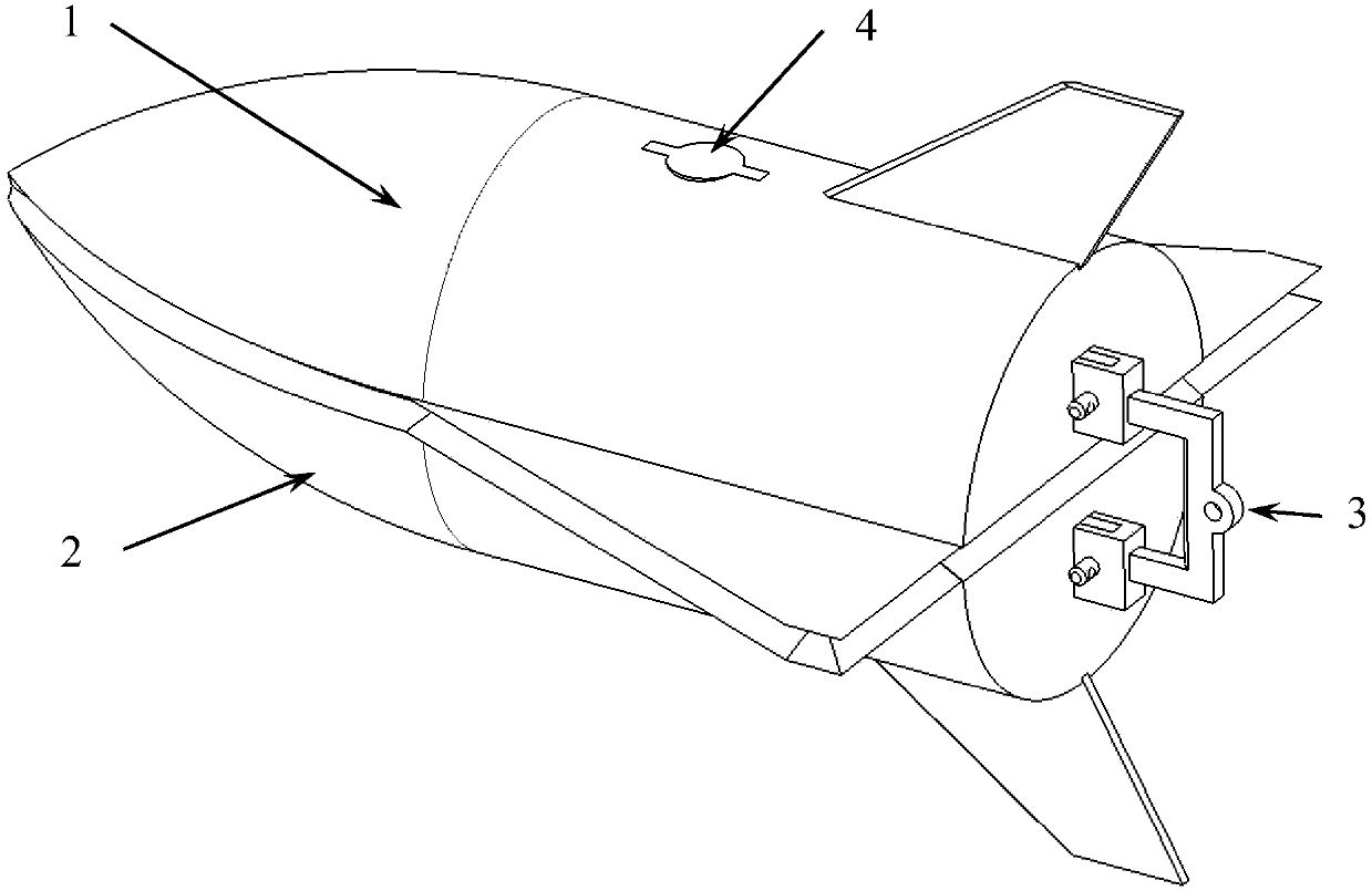
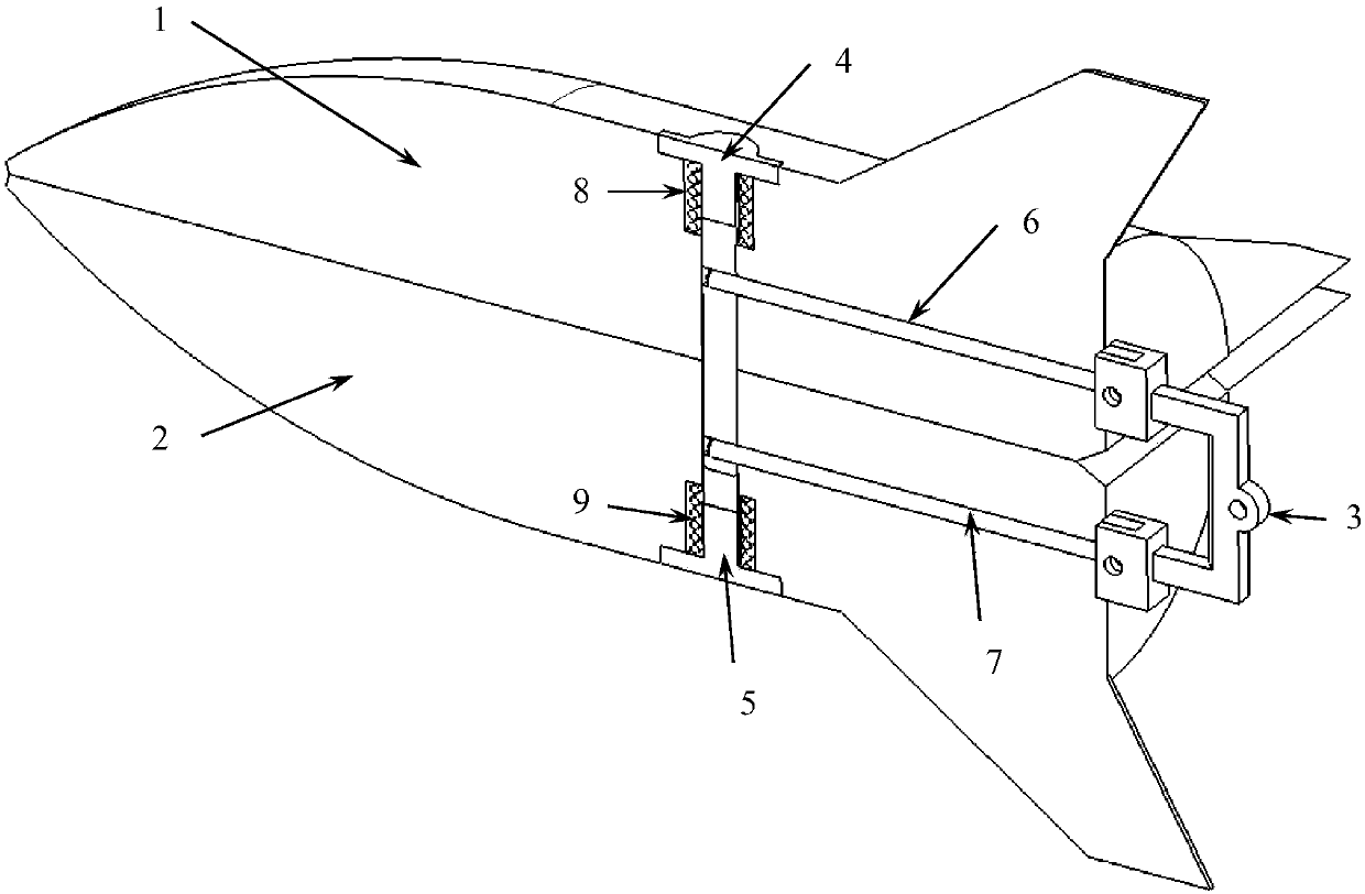
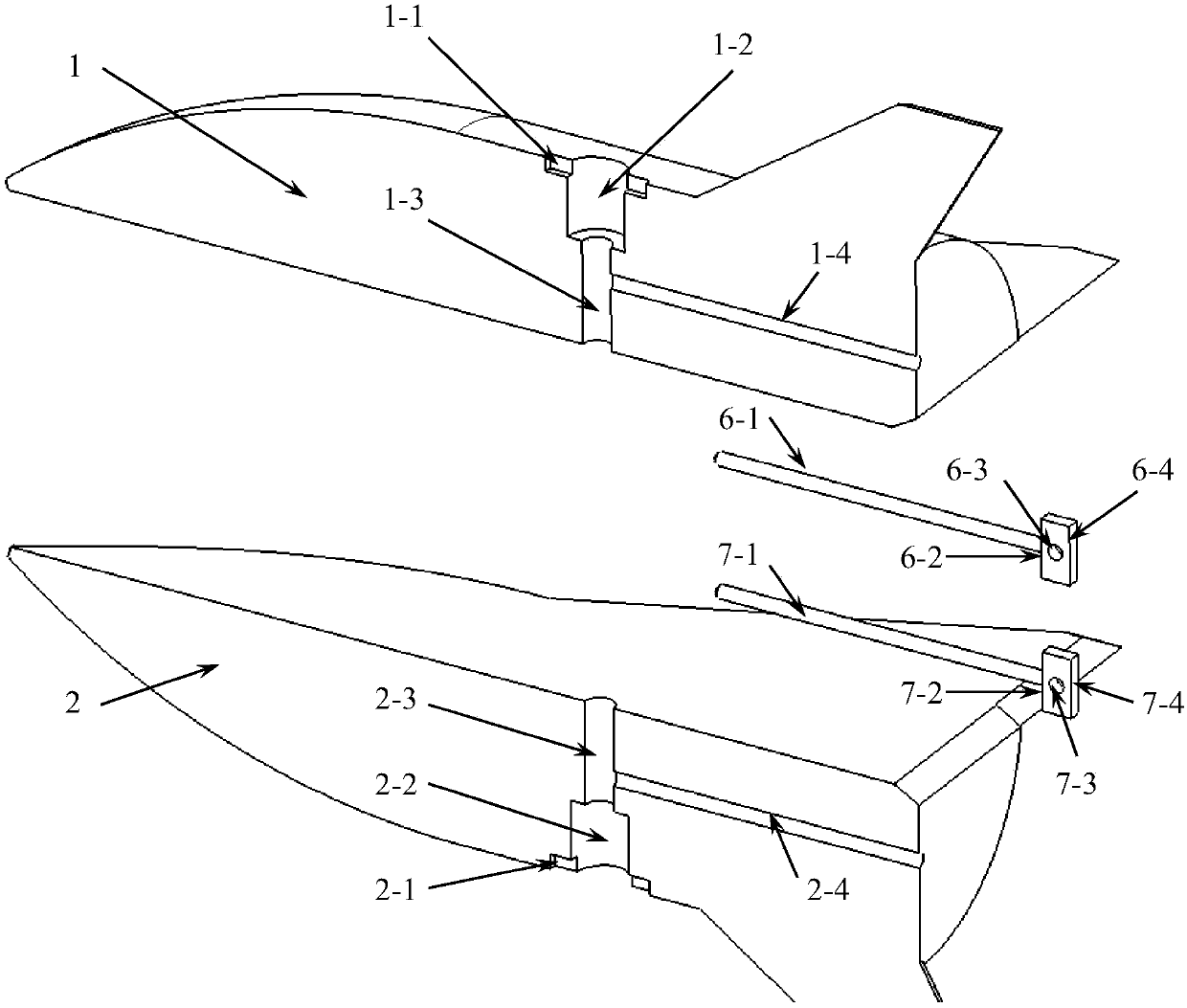
[0027] Such as figure 1 , figure 2 As shown, a parallel inter-stage separation free-flying wind tunnel test device with the center of mass located at the interface includes a first model 1, a second model 2, a pin holder 3, a first fixing nail 4, a second fixing nail 5, The first pull pin 6, the second pull pin 7, the first spring 8, the second spring 9, the pin 10; the pin pull frame 3 is connected with the first pull pin 6 and the second pull pin 7 respectively, and the primary fixing nail 4, Insert the first model 1 through the first spring 8, and insert the secondary fixing nail 5 into the second model 2 through the second spring 9; 2 Insert the end face of the tail into the first model 1 and the second model 2, so that the first model 1 and the second model 2 are dock...


PUM


Abstract

A parallel stage separation free flight wind tunnel testing device with the mass center located on the interface comprises a first model, a second model, a pull pin frame, pins, a first fixing nail, asecond fixing nail, a first spring, a second spring, a first pull pin and a second pull pin. The first pull pin, the second pull pin and the pull pin frame are installed together through the two pins, the first fixing nail and the second fixing nail penetrate through respective springs and are inserted into the first model and the second model, and the pull pins installed just are inserted into the models from the model tails and are just inserted into a round hole formed by a semi-circular groove of the first fixing nail and a round hole formed by a semi-circular groove of the second fixingnail to lock the whole model set. It is ensured that the first model and the second model can be fast and effectively separated without interference, the problem that a parallel stage separation freeflight wind tunnel test with the mass center located on the interface cannot be realized is solved mainly, and the defect that two stages cannot release the freedom degree at the same time due to theprevious model fixing mode is overcome.

Description

technical field [0001] The invention relates to a free-flying wind tunnel test device for separation between parallel stages. Background technique [0002] The model free-flying wind tunnel test is a commonly used research method to study the dynamic aerodynamic characteristics of aircraft, and it can also be used in the research of aircraft multi-body interference. The basic method of the test is to eject the model at high speed against the direction of the airflow after the flow field in the wind tunnel is stabilized. The model will fly freely in the wind tunnel for a short time to test the safety of the separation of the multi-stage aircraft. At the same time, high-speed photography is used to monitor the model through the observation window. After shooting, the attitude trajectory of the aircraft model flying freely can be obtained, and the dynamic aerodynamic parameters of the aircraft can be obtained after data processing in the later stage. The separation between the...

Claims


Application Information

Patent Timeline
Patent Type & Authority Applications(China)
IPC IPC(8): G01M9/04G01M9/08
CPCG01M9/04G01M9/08
Inventor 薛飞王誉超杨益农蒋增辉
Owner CHINA ACAD OF AEROSPACE AERODYNAMICS
Why Eureka
Try Eureka