A reticle y-direction positioning device and method and a reticle transfer system

The technology of a positioning device and a transmission system is applied to the exposure device of the photoplate making process, the photoplate making process of the pattern surface, the microlithography exposure equipment, etc., and can solve the problems of easy damage and large force when positioning the reticle. To achieve the effect of protection from damage

Active Publication Date: 2020-04-10
SHANGHAI MICRO ELECTRONICS EQUIP (GRP) CO LTD
View PDF4 Cites 0 Cited by
  • Summary
  • Abstract
  • Description
  • Claims
  • Application Information

AI Technical Summary

Problems solved by technology

[0005] The purpose of the present invention is to provide a reticle Y-direction positioning device and method and a reticle transport system to solve the problem that the existing reticle is easily damaged when the force is too large

Method used


Image

  • A reticle y-direction positioning device and method and a reticle transfer system
  • A reticle y-direction positioning device and method and a reticle transfer system
  • A reticle y-direction positioning device and method and a reticle transfer system

Examples


Embodiment 1

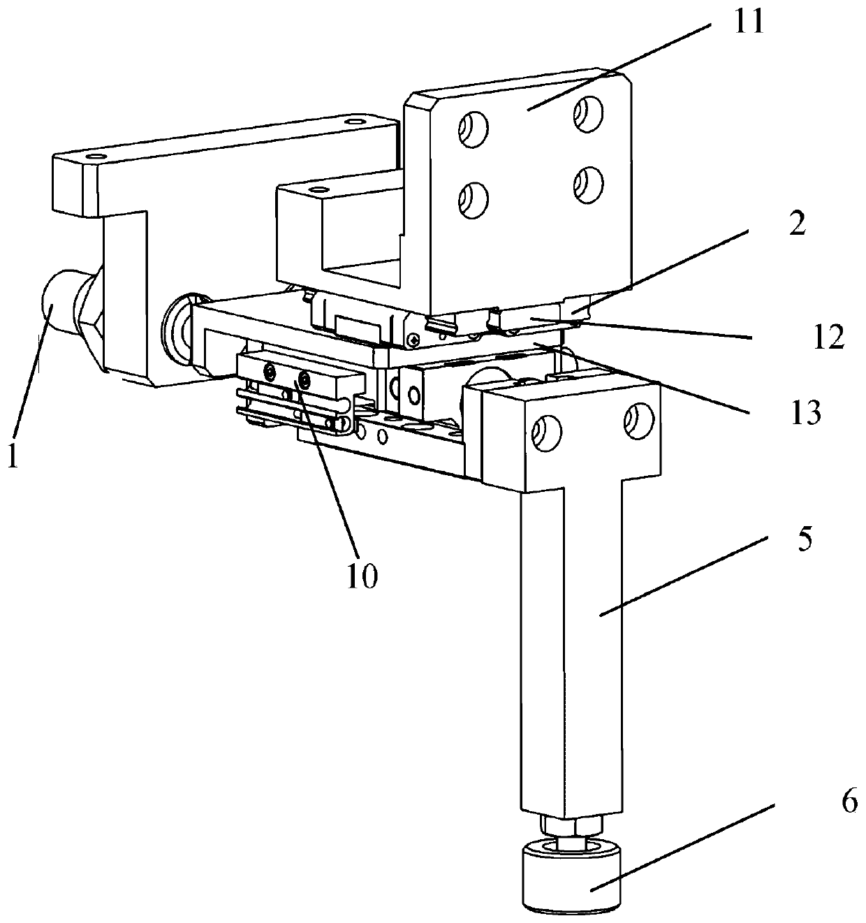
[0036] figure 1 It is a three-dimensional structural diagram of the reticle Y-direction positioning device in Embodiment 1 of the present invention. Please refer to figure 1 , this embodiment 1 provides a reticle Y-direction positioning device, including an over-position protection structure and a push rod structure, and the over-position protection structure pushes the push rod structure to move in the direction where the reticle is located and absorbs excess force on the reticle .

[0037] Specifically, the over-position protection structure includes: an elastic component 1 , a guide rail slider 2 and a driving element 10 , one end of the driving element 10 is connected to the elastic component 1 , and the other end is connected to the guide rail slider 2 . Further, in this embodiment, the elastic assembly 1 may be a spring assembly, and the driving element 10 may be an air cylinder, that is, one end of the spring assembly is connected to the air cylinder, and one end of t...

Embodiment 2

[0043] The main difference between embodiment 2 and embodiment 1 is that in embodiment 2, the spring assembly in embodiment 1 is replaced by a rubber assembly, and the position and connection relationship of each element remain unchanged.

[0044] Please continue to refer figure 1 , Embodiment 2 provides a Y-direction positioning device for a reticle, including an over-position protection structure and a push rod structure, and the over-position protection structure pushes the push rod structure to move toward the direction of the reticle and absorbs excess force on the reticle.

[0045]Specifically, the over-position protection structure includes: an elastic component 1 , a guide rail slider 2 and a driving element 10 , one end of the driving element 10 is connected to the elastic component 1 , and the other end is connected to the guide rail slider 2 . Further, in this embodiment, the elastic component 1 may be a rubber component, and the driving element 10 may be an air cyl...

Embodiment 3

[0050] The main difference between embodiment 3 and embodiment 1 is that the electric cylinder is used to replace the air cylinder in embodiment 1 in embodiment 3, and the position and connection relationship of each component remain unchanged.

[0051] Please continue to refer figure 1 , Embodiment 3 provides a Y-direction positioning device for a reticle, including an over-position protection structure and a push rod structure, and the over-position protection structure pushes the push rod structure to move toward the direction of the reticle and absorbs excess force on the reticle.

[0052] Specifically, the over-position protection structure includes: an elastic component 1 , a guide rail slider 2 and a driving element 10 , one end of the driving element 10 is connected to the elastic component 1 , and the other end is connected to the guide rail slider 2 . Further, in this embodiment, the elastic component 1 can be a spring component, and the driving element 10 can be an ...


PUM


Abstract

The invention provides a mask Y-direction positioning device and method a mask conveying system. The device comprises a push rod structure and a position-passing protection structure, and the position-passing protection structure pushes the push rod structure to move in the direction of a mask and absorbs surplus acting force of the mask during Y-direction positioning to protect the mask from being damaged. The device is applied in the mask conveying system which comprises the mask Y-direction positioning device, a mask fetching and releasing manipulator, a mask fetching and releasing manipulator fork and a mask exchange manipulator, and the mask fetching and releasing manipulator fork is driven by the mask fetching and releasing manipulator to move in a direction of the mask Y-direction positioning device and to enable the mask to contact with the device. Aiming at weak links in the process of positioning the mask, the Y-direction positioning device is added, so that positioning needsof the mask are met, the surplus acting force given by the mask fetching and releasing manipulator fork is absorbed effectively, and the mask is protected from being damaged.

Description

technical field [0001] The invention relates to the technical field of semiconductor manufacturing, in particular to a Y-direction positioning device and method for a reticle and a reticle transmission system. Background technique [0002] As an important part of the mask transmission system of the lithography machine, the plate exchange manipulator has high requirements on the positioning accuracy of the mask plate. In the existing mask transfer process, since the reticle is relatively small, the requirements for reticle positioning are relatively low. In the flat panel display manufacturing process, as the size of the reticle continues to increase, the requirements for reticle positioning are relatively low. is also improving. [0003] Specifically, in the mask transfer system, when the pick-and-place manipulator fork transports the reticle to the mask transfer position, it is necessary to perform rough positioning in the Y direction on the reticle placed on the pick-and-...

Claims


Application Information

Patent Timeline
Patent Type & Authority Patents(China)
IPC IPC(8): G03F7/20
CPCG03F7/707G03F7/70733G03F7/70783
Inventor 马方波吴福龙
Owner SHANGHAI MICRO ELECTRONICS EQUIP (GRP) CO LTD
Why Eureka
Try Eureka