
Shear test method of rock structural plane and its implementing device

A technology of shear test and structural surface, applied in the direction of applying stable shear force to test the strength of materials, etc., can solve the problems of structural surface damage, test failure, troubled rock structural surface shear test, etc., to promote progress and development , Reliable measurement results and convenient measurement

Active Publication Date: 2016-02-10
SICHUAN UNIV
View PDF4 Cites 0 Cited by
  • Summary
  • Abstract
  • Description
  • Claims
  • Application Information

AI Technical Summary

Problems solved by technology

However, due to the low strength of the structural surface itself, it is easy to cause damage to the structural surface during the pouring process of the specimen or during the handling process before shearing after pouring, resulting in the failure of the test
In addition, the rock containing the structural surface is poured into a regular specimen with cement. Since the cement has a great influence on the measurement of the shear deformation and shear strength of the structural surface, the measurement results must exclude the influence of cement, and the influence of cement is also It is difficult to measure accurately, so it makes the test measurement process of the rock structural plane complicated, the measurement results are poor in accuracy and reliability, and the real shear strength parameters of the rock structural plane cannot be obtained
This problem has long plagued the shear test of rock structural planes

Method used


Image

  • Shear test method of rock structural plane and its implementing device
  • Shear test method of rock structural plane and its implementing device
  • Shear test method of rock structural plane and its implementing device

Examples


Embodiment 1

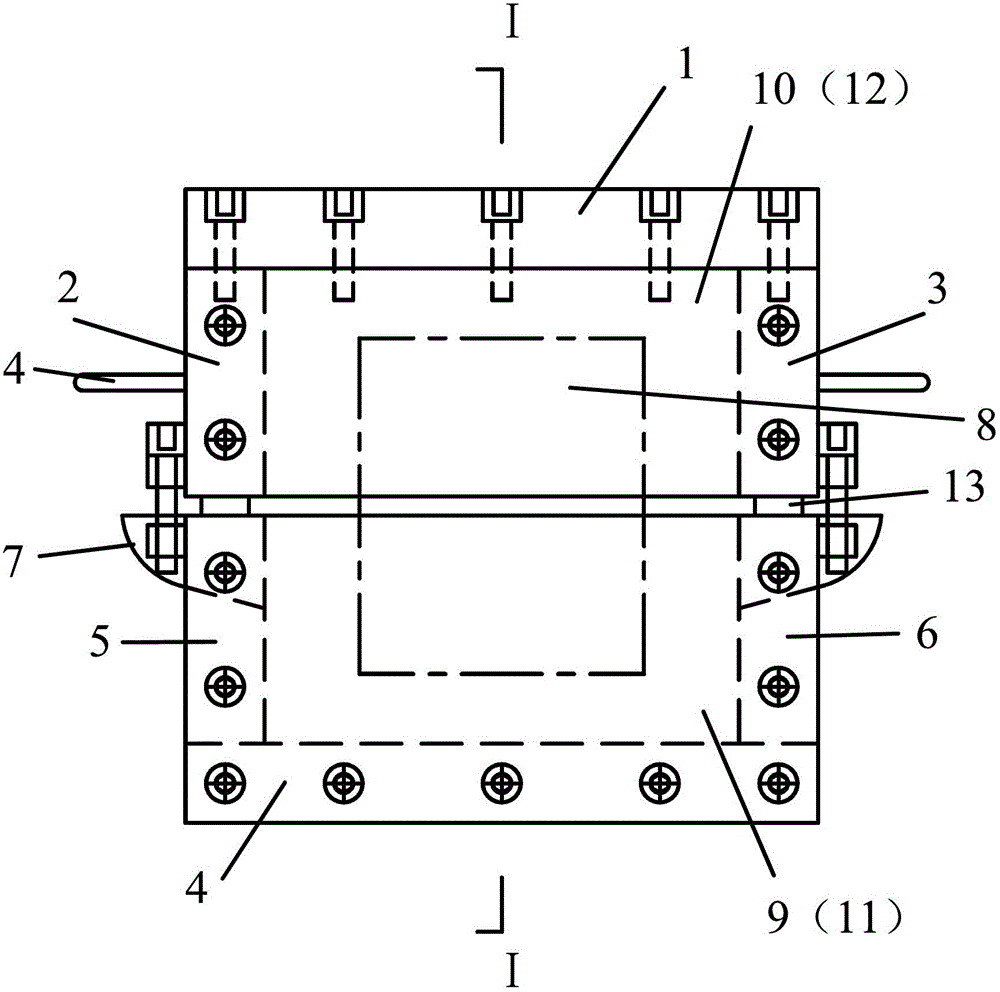
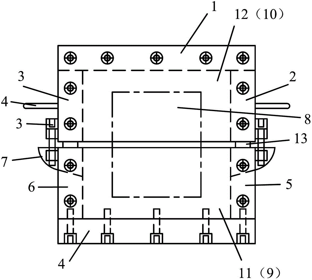
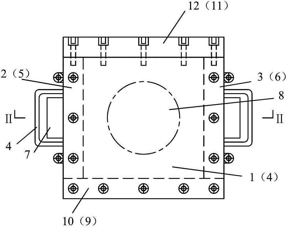
[0031] The structure of the rock structural surface shear test device of this embodiment is as follows: figure 1 to attach Figure 6 As shown, it consists of two upper and lower opening shear boxes matching the upper and lower parts of the rock sample test block 8. The upper and lower opening shear boxes are all combined structures, and are fixed and assembled by five box body plates through countersunk bolts. Integral, the box body plate surface on the side where the shear force is applied is crimped to the end surface of the box body plate in the other direction. The box body plate on which the upper shear box applies shear force is the rear side box body plate 12 , and the box body plate on which the lower shear box applies shear force is the front side box body plate 9 . The upper top box body plate 1 of the upper shear box is crimped to the box body plate end faces in the other three directions, and the lower bottom box body plate 4 of the lower shear box is crimped to t...


PUM


Abstract

The invention discloses a rock structural surface shear test method and an implementation apparatus thereof. The method mainly comprises the steps that: an upper part and a lower part of a rock sample are respectively fixed in an upper opened shearing box and a lower opened shearing box with opposite opening surfaces through filling, wherein a certain distance is kept between the opening surfaces of the upper and lower shearing boxes, such that the rock sample block shear test structural surface is exposed between the opening surfaces of the upper and lower shearing boxes; a pair of shear loads with opposite directions are implemented on the upper and lower shearing boxes, and the loads act upon the rock sample block through the filling materials in the shearing boxes; the loads further act upon the rock sample block structural surface, such that the shear strength parameter of the rock sample block structural surface is obtained. According to the invention, the rock structural surface is subjected to a shear test, such that structural surface damage of the rock sample block during a moving process is effectively avoided, and test failure caused by damaged structural surface is prevented. The influence of cement upon sample block tests in prior arts is completely eliminated, and the true shear strength parameter of the rock structural surface can be obtained.

Description

technical field [0001] The invention relates to the technical field of rock mechanical performance tests, in particular to a method and device for a shear test of a rock structural surface. Background technique [0002] Rock is an important environmental geology and very important engineering material involved in engineering construction. In order to ensure engineering quality and engineering safety, it is necessary to understand the various strengths of rocks, especially the shear strength, during engineering construction. The rock structural plane is a weak shearing surface of the rock, and its shear strength is usually very low. A slight disturbance can easily cause damage along the structural plane. Therefore, after sampling on site, the rock containing the structural plane cannot be processed into Regular specimens that can be directly sheared. In practice, cement is usually used to pour rocks containing structural surfaces into regular specimens, and then shear tests a...

Claims


Application Information

Patent Timeline
Patent Type & Authority Patents(China)
IPC IPC(8): G01N3/24
Inventor 刘建锋谢和平徐进鞠杨裴建良张茹邓建辉王璐
Owner SICHUAN UNIV
Learn More