
CAN bus-based multi-node automatic networking method

A CAN bus and automatic networking technology, applied in the field of CAN bus, can solve problems such as limited application occasions, increased operation difficulty, and increased host monitoring difficulty

Active Publication Date: 2018-03-09
FSP POWERLAND TECH
View PDF2 Cites 15 Cited by
  • Summary
  • Abstract
  • Description
  • Claims
  • Application Information

AI Technical Summary

Problems solved by technology

[0005] 1) The starting node needs to be selected externally, which increases the difficulty of operation and is not fully automatic;
[0006] 2) The node ID is determined by a random number, which will cause discontinuity and increase the difficulty of host monitoring;
[0007] 3) The total number of network nodes N needs to be determined to determine the completion of the network, and the application occasions are limited; it is also impossible to dynamically increase or decrease the network nodes
[0009] 1) Each node, that is, a terminal device, must have a different characteristic ID, and the ID cannot be automatically assigned; only through networking to compete for the bus controller;
[0010] 2) The bus controller must maintain the node information table. If the bus controller exits, the network needs to be re-established. The new competitive bus controller maintains the node information table, which increases the difficulty of software development

Method used

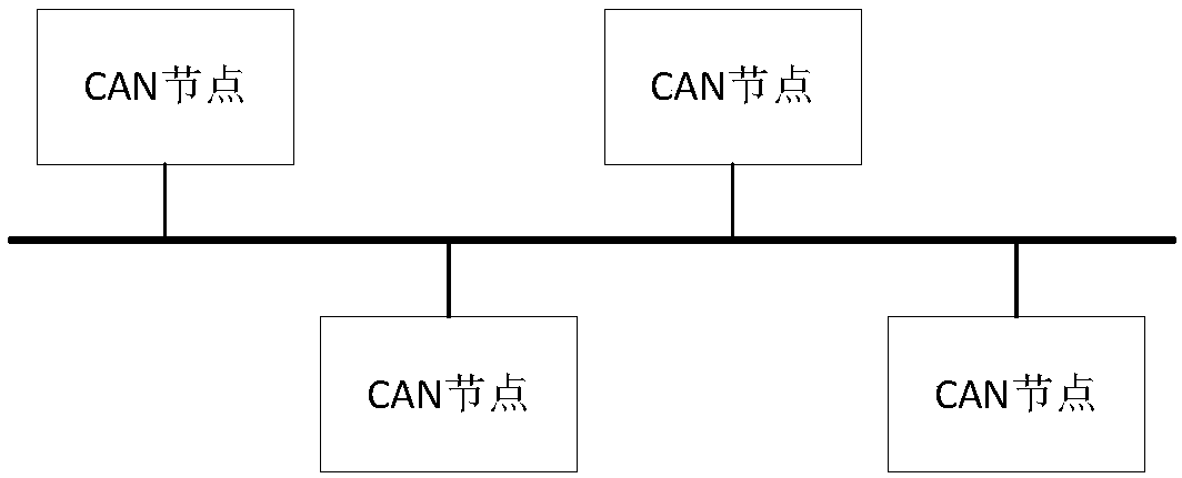

Image

  • CAN bus-based multi-node automatic networking method
  • CAN bus-based multi-node automatic networking method
  • CAN bus-based multi-node automatic networking method

Examples


no. 1 example

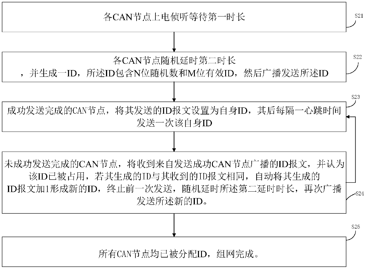
[0039] figure 2 For the first embodiment of CAN bus dynamic networking method of the present invention, comprise the steps:

[0040] Step S21 , each CAN node is powered on and waits for a first duration of listening. Used to receive ID messages on the bus. The first duration is, for example, 1S.

[0041] In step S22, each CAN node randomly delays for a second time length, and generates an ID, the ID includes a random number of N bits and an effective ID of M bits, and then broadcasts the ID. The ID sent by broadcast is an ID message. Such as image 3 It is composed of the standard frame of the ID described in the present invention, the number of digits of the standard frame of the ID is N+M bits, preferably, the number of digits of the standard frame of the ID is 11 digits, and wherein N is preferably N<6 , and the initial effective ID of each node is 1. In addition, the second duration is preferably less than 100ms.

[0042] Step S23 , the CAN node that has successful...


PUM


Abstract

The invention discloses a CAN bus-based multi-node automatic networking method. A CAN node is electrified to intercept and wait for a first duration, randomly postpones for a second duration and obtains an ID, and then, sends the ID through broadcasting. The CAN node successfully sending the ID through broadcasting sets the sent ID as an own ID, and then, sends the own ID one time at each heartbeat time. The node which cannot successfully send the ID receives an ID message broadcasted by the CAN node successfully sending the ID, and considers that the ID is occupied, adds 1 to the ID to form anew ID, stops last sending, randomly postpones for the second duration, and sends the new ID message again through broadcasting. By analogy, until all the CAN nodes are allocated with the ID. The automatic networking method provided by the invention aims at applications where multiple machines are connected in parallel and a plurality of nodes are on the bus, through an automatic networking algorithm, realizes ID allocation and dynamic increase and decrease of nodes, and has no need of any artificial or external intervention.

Description

technical field [0001] The invention relates to the field of CAN bus technology, and in particular to a method for automatic networking of the CAN bus. Background technique [0002] CAN (Controller Area Network) bus is a serial digital communication bus originally designed for the control of automotive on-board equipment. cable routing. Due to the high reliability, refined protocol and low price of the CAN bus, it is also widely used in the field of industrial measurement and control. With the popularization of electric vehicles, the charging pile market is huge. In order to facilitate the connection with the battery management system BMS, the CAN bus has also become the mainstream communication method in charging pile products. [0003] Charging piles generally consist of several or dozens of charging modules connected in parallel to increase power, and communication power systems are usually composed of several switching power supply modules connected in parallel, and th...

Claims


Application Information

Patent Timeline
Patent Type & Authority Applications(China)
IPC IPC(8): H04L12/40H04L12/413H04L29/12
CPCH04L12/40H04L12/413H04L2012/40215H04L61/5038H04L61/5069H04L2101/627
Inventor 李晓庆陈世明
Owner FSP POWERLAND TECH
Learn More