Pipe fitting flattening and flaring tool

A technology of pipe fittings and tools, which is applied in the field of pipe fitting flattening and flaring tools, can solve the problems of affecting work efficiency, increasing costs, uncertainties, etc., and achieve the effect of reducing mold change time and improving work efficiency

Active Publication Date: 2018-03-13
ZHEJIANG MOTORBACS TECH
View PDF6 Cites 6 Cited by
  • Summary
  • Abstract
  • Description
  • Claims
  • Application Information

AI Technical Summary

Problems solved by technology

[0002] In the prior art, the flattening and flaring processes of pipe fittings are carried out independently in the tube crimping mold and the flaring mold respectively, and at least two driving mechanisms are required to respectively drive the crimping mold and the flaring mold to close the molds. On the one hand, the work efficiency is not high, on the other hand, it also increases the cost
In addition, the molds in the prior art need to be adjusted and corrected during assembly to ensure that the upper and lower molds are aligned. This adjustment and calibration process is quite time-consuming and labor-intensive, which affects work efficiency
In addition, pipe fittings are generally made by rolling plates, and then the first and last ends of the rolled plates are welded to form pipes. In order to determine the firmness of the welding, it is necessary to test the strength of the welds of the pipe fittings, and the welds The strength test is generally carried out through the pipe crimping process, that is, the pipe fittings are flattened to a certain extent, and whether the weld seam strength meets the requirements is judged by observing whether the weld seam is broken and whether the center line of the weld seam is offset, but now it is usually through Workers visually judge whether the centerline of the weld seam has shifted during the flattening process. This detection method has large errors and uncertainties.

Method used


Image

  • Pipe fitting flattening and flaring tool
  • Pipe fitting flattening and flaring tool

Examples


Embodiment Construction

[0025] The present invention will be further described in detail below with reference to the embodiments of the accompanying drawings.

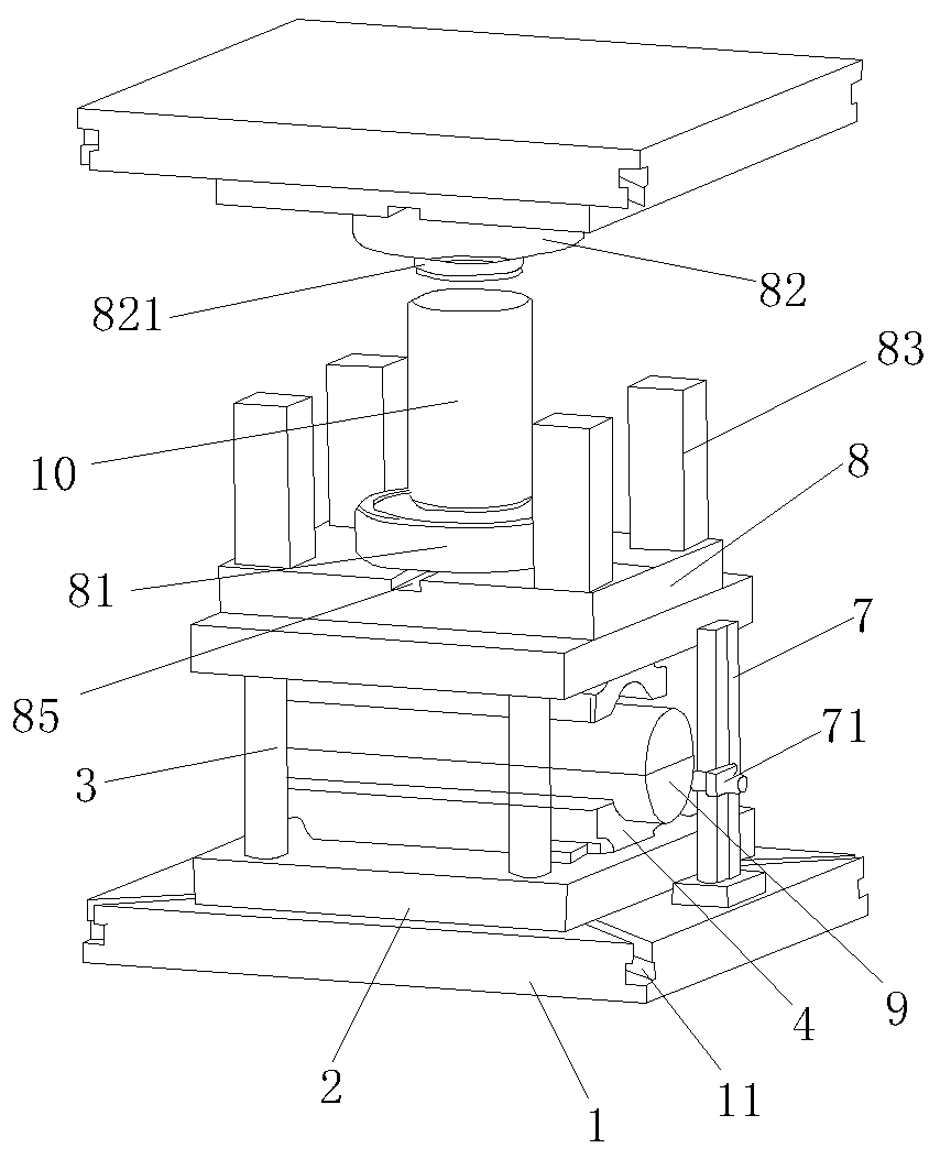
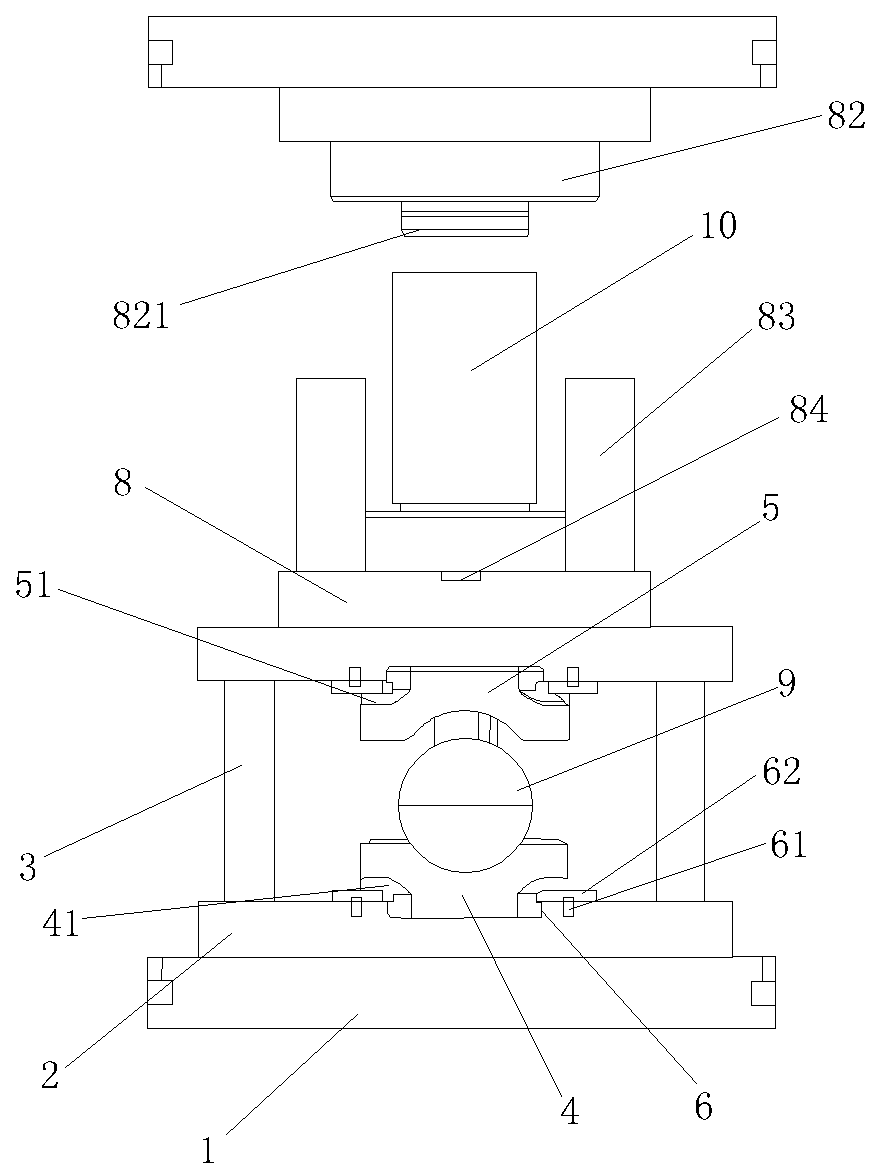
[0026] As shown in the accompanying drawings, this embodiment is a flattening and flaring tool for pipe fittings, which includes a flaring station and a pipe crimping station. The flaring station is located directly above the pipe crimping station. The upper and lower positions of the two are They can be interchanged with each other, but because the mold used for crimping pipes is heavier than the mold used for pipe flaring, generally the flaring station is set above the crimping station.

[0027] The pipe crimping station includes a base plate 1, on which two crossed chute 11 is opened, the chute forms an entrance on the edge of the base plate, and a backing plate 2 is fixed on the bottom plate, and the backing plate is clamped. It is detachably fixed on the top of the bottom plate. Specifically, the bottom of the backing plate is formed wit...


PUM


Abstract

The invention discloses a pipe fitting flattening and flaring tool. Flattening weld inspection and pipe end flaring of pipe fittings can be realized by a spotting force at the same time, and accordingly, working efficiency is improved; a rapid die changing structure is arranged in the tool, and dies can be replaced rapidly and accurately, so that working efficiency is improved remarkably, and diechanging time is reduced; a grating ruler is arranged in the pipe fitting flattening and flaring tool, and central positions of weld joints can be detected accurately.

Description

technical field [0001] The invention relates to the technical field of pipe making, in particular to a pipe fitting flattening and flaring tool capable of performing flattening welding seam detection and pipe end flaring on a pipe fitting at the same time. Background technique [0002] In the prior art, the flattening and flaring processes of pipe fittings are carried out independently in the tube crimping mold and the flaring mold respectively, and at least two driving mechanisms are required to respectively drive the crimping mold and the flaring mold to close the molds. On the one hand, the work efficiency is not high, on the other hand, it also increases the cost. In addition, the molds in the prior art need to be adjusted and corrected during assembly to ensure that the upper and lower molds are aligned. This adjustment and calibration process is quite time-consuming and labor-intensive, which affects work efficiency. In addition, pipe fittings are generally made by ro...

Claims


Application Information

Patent Timeline
Patent Type & Authority Applications(China)
IPC IPC(8): B21D31/00B21D41/02B21D37/10B21C51/00
CPCB21C51/00B21D31/00B21D37/10B21D41/02
Inventor 陆志伟罗宇飞
Owner ZHEJIANG MOTORBACS TECH
Why Eureka
Try Eureka