Overturning device for sanding machine
A technology of sanding machine and turning over surface, which is applied in the direction of conveyor objects, transportation and packaging, grinding machine parts, etc. Lift the flip effect
- Summary
- Abstract
- Description
- Claims
- Application Information
AI Technical Summary
Problems solved by technology
Method used
Image
Examples
Embodiment 1
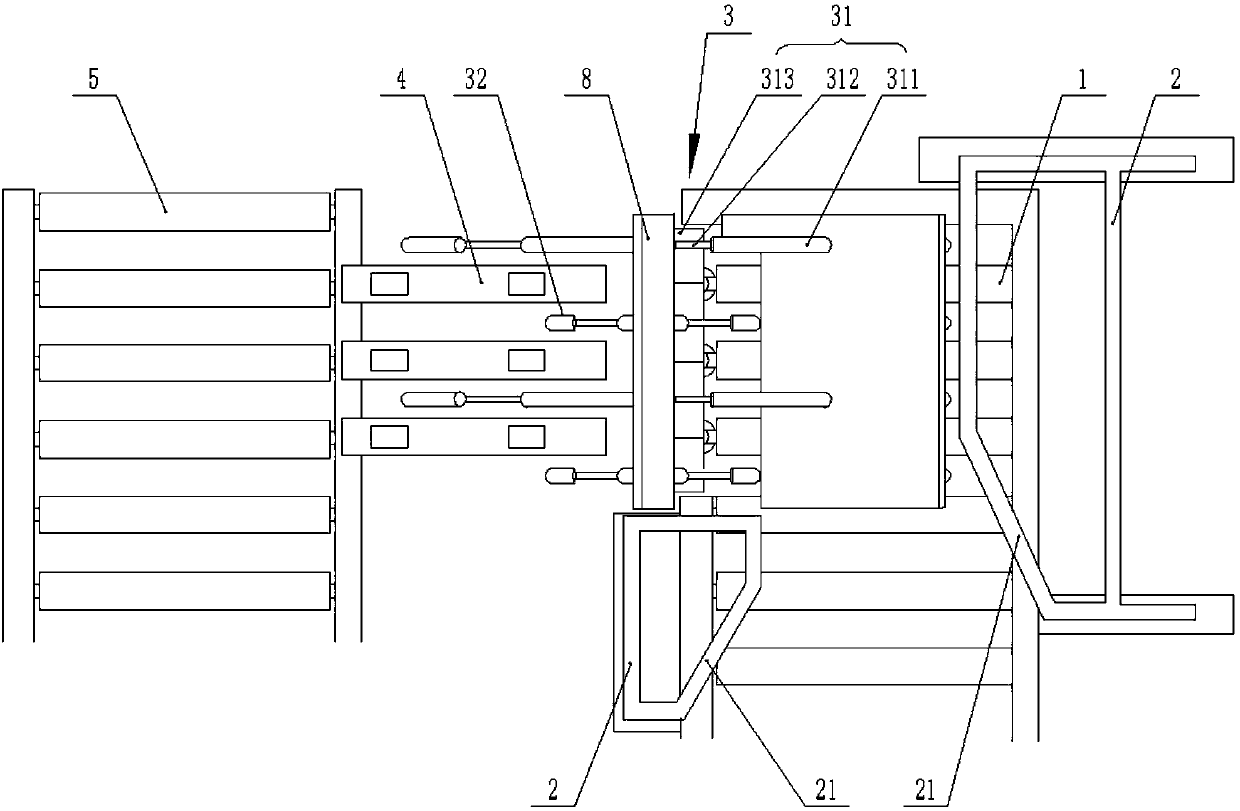
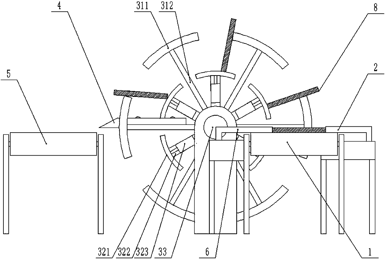
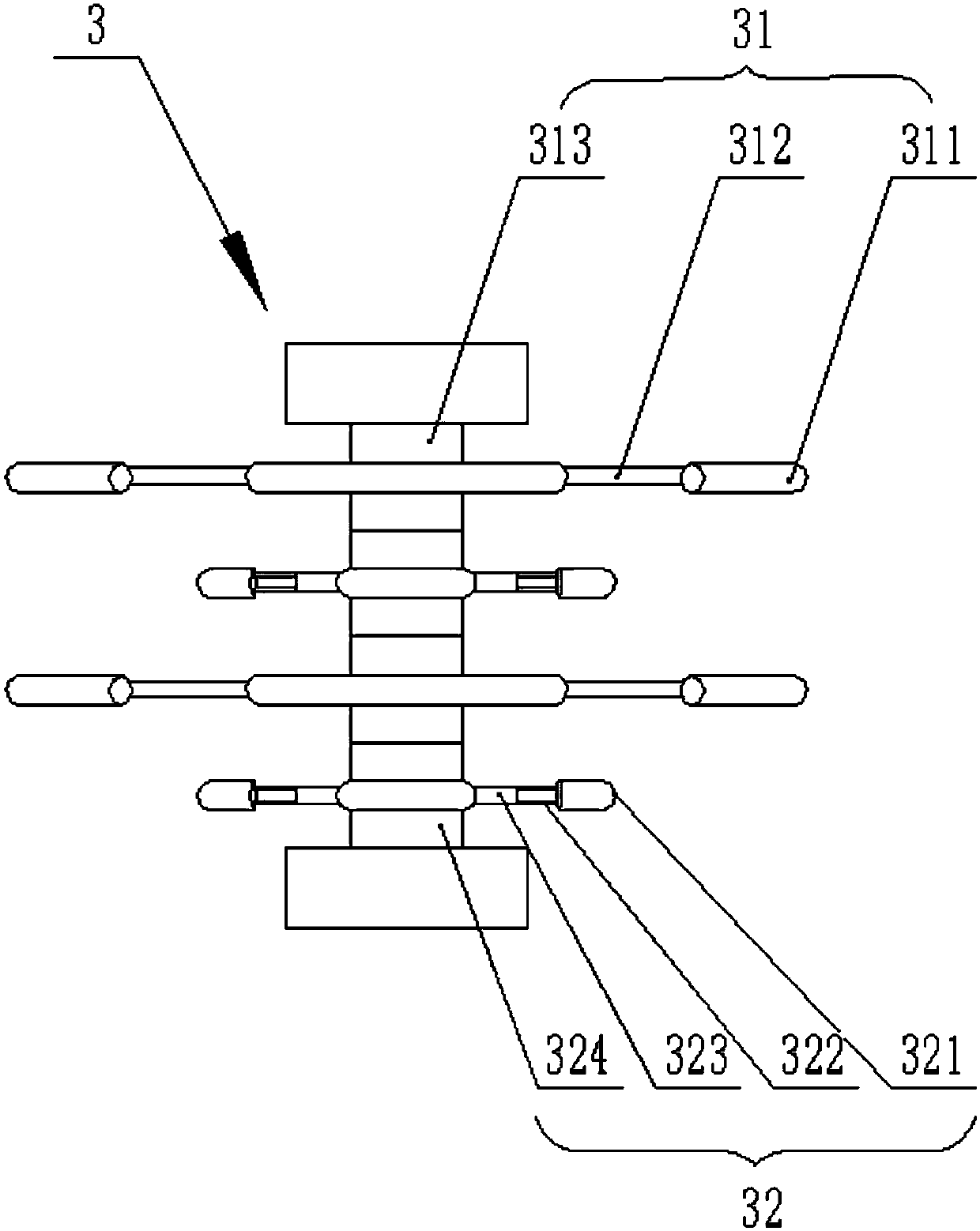
[0022] see figure 1 , figure 2 , In a preferred embodiment of the present invention, a surface turning device for a sander includes a first conveying roller device 1 and a second conveying roller device 5 arranged in parallel. Both the first conveying roller device 1 and the second conveying roller device 5 are provided with a plurality of parallel rollers, and a gap is provided between two adjacent rollers. The first transfer roller device 1 is provided with a turnover device 3, and the turnover device 3 includes a turnover wheel 31, an adjustment wheel 32 and a drive shaft 33, and there are several turnover wheels 31 and adjustment wheels 32 and are arranged on the drive shaft in turn. 33, the turning wheel 31 and the adjusting wheel 32 are arranged at intervals. In this embodiment, the number of turning wheels 31 is 2, and it is easy to understand that the number of turning wheels 31 may be any of 2 to 8. In this embodiment, the number of adjustment wheels 32 is 2, and ...
Embodiment 2
[0025] see image 3 , Figure 4 , in a preferred embodiment of the present invention, a kind of turning device for sanding machine, the key on the second hub 324 cooperates with the drive shaft 33 through another key groove, so that the connection plate 322 is in the radial direction of the drive shaft 33 The direction is the same as that of the connecting rod 312, and the end faces of the lifting block 311 and the arc bar 321 can simultaneously support the board surface of the plank. The rest are as described in Example 1.
[0026]Briefly describe the working principle and usage method of the present invention: the wooden board 8 moves on the first conveying roller device 1 , and the wooden board 8 is guided to a suitable position on the first conveying roller device 1 by the block frame 2 . When the wooden board 8 moved to the position of the upper limit of the first conveying roller device 1, there was a lifting block 311 at the bottom of the roller gap to rotate and move...
PUM
 Abstract
Description
Claims
Application Information
 - R&D
- Intellectual Property
- Life Sciences
- Materials
- Tech Scout
- Unparalleled Data Quality
- Higher Quality Content
- 60% Fewer Hallucinations
Browse by: Latest US Patents, China's latest patents, Technical Efficacy Thesaurus, Application Domain, Technology Topic, Popular Technical Reports.
© 2025 PatSnap. All rights reserved.Legal|Privacy policy|Modern Slavery Act Transparency Statement|Sitemap|About US| Contact US: help@patsnap.com


