Supercharge Your Innovation With Domain-Expert AI Agents!

A gas turbine cooling air distribution system

A technology of gas turbine and distribution system, which is applied in the direction of gas turbine device, engine cooling, turbine/propulsion device cooling, etc. It can solve the problem that the gas supply pipeline cannot meet the volume and weight of the equipment, so as to reduce the length, weight and requirements Effect

Active Publication Date: 2019-08-06
AECC COMML AIRCRAFT ENGINE CO LTD
View PDF6 Cites 0 Cited by
  • Summary
  • Abstract
  • Description
  • Claims
  • Application Information

AI Technical Summary

Problems solved by technology

In order to achieve the effect of uniform distribution of cooling air, thicker air supply pipelines are usually required. However, in the design and construction of gas turbines, especially aero-engines, thicker air supply pipelines cannot meet the requirements for equipment volume and weight

Method used


Image

  • A gas turbine cooling air distribution system
  • A gas turbine cooling air distribution system
  • A gas turbine cooling air distribution system

Examples


Embodiment Construction

[0021] The present invention will be further described below in conjunction with specific embodiment and accompanying drawing, set forth more details in the following description so as to fully understand the present invention, but the present invention can obviously be implemented in many other ways different from this description, Those skilled in the art can make similar promotions and deductions based on actual application situations without violating the connotation of the present invention, so the content of this specific embodiment should not limit the protection scope of the present invention.

[0022] have to be aware of is, Figure 1 to Figure 4 All are for example only, and they are not drawn in accordance with the same scale conditions, and should not be taken as limitations on the protection scope of the actual claims of the present invention.

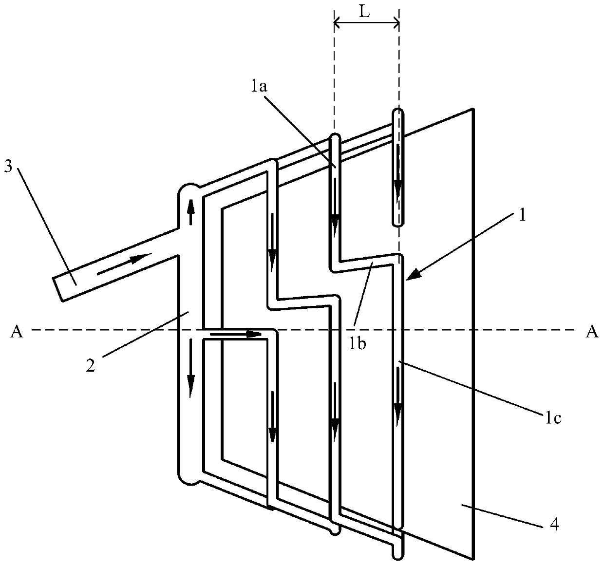
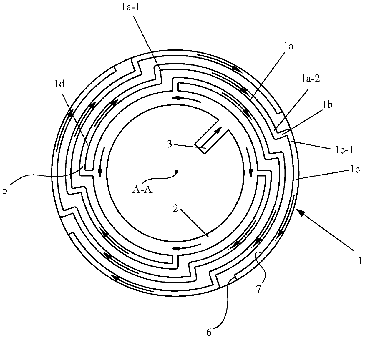
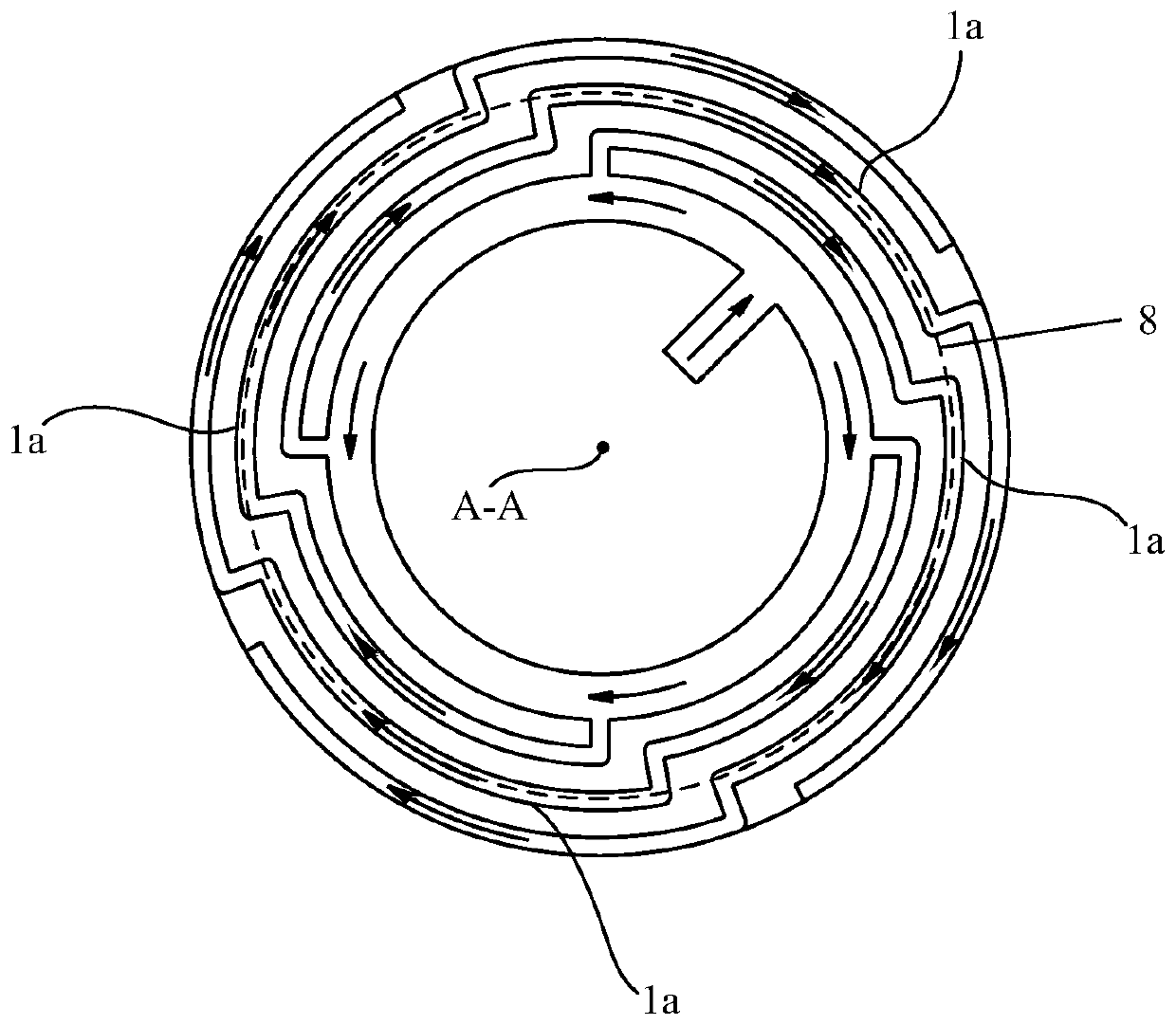
[0023] In the present invention, the axial direction refers to the direction of the axis line A-A of the casing 4, the r...


PUM


Abstract

A purpose of the present invention is to provide a gas turbine cooling gas distribution system, wherein the uniform circumferential distribution of cooling gas is achieved by using simple pipeline design while the weight and the volume of the cooling gas pipeline can be reduced. According to the present invention, the cooling pipeline of the gas turbine cooling gas distribution system has a plurality of impact pipes with the same structure, and the distances between the initial inlet ends and the blind ends of the impact pipes are equal, such that the uniform circumferential distribution of cooling gas is easily achieved, the length of the impact pipe is reduced, and the requirement of the gas turbine cooling gas distribution system on the diameter of the impact pipe is reduced, wherein the small pipeline diameter can be used so as to reduce the weight of the pipeline.

Description

technical field [0001] The invention relates to the field of aero-engines, in particular to a gas turbine cooling air distribution system. Background technique [0002] Gas turbines operate at different gas temperatures, which vary depending on the power setting as well as the environment. These gases at different temperatures heat the rotor and casing. Due to the different thermal expansion characteristics of the rotor and the casing, the gap between the blade tip and the casing (tip clearance) will change with the operating state of the engine. When the engine is running, centrifugal action also causes the rotor to elongate radially. Excessive tip clearance will reduce the efficiency of the gas turbine, and too small tip clearance will cause the blades and the inner wall of the casing to scrape against each other. [0003] In order to prevent these situations from happening, it is very necessary to control the thermal expansion of the gas turbine case. Cooling the case...

Claims


Application Information

Patent Timeline
Patent Type & Authority Patents(China)
IPC IPC(8): F02C7/18
CPCF02C7/185
Inventor 陈少杰顾伟
Owner AECC COMML AIRCRAFT ENGINE CO LTD
Features
  • R&D
  • Intellectual Property
  • Life Sciences
  • Materials
  • Tech Scout
  • Unparalleled Data Quality
  • Higher Quality Content
  • 60% Fewer Hallucinations
Learn More