Brake cylinder clearance adjusting mechanism and brake cylinder

A gap adjustment mechanism and brake cylinder technology, applied in the direction of brake types, brake parts, axially joined brake parts, etc., can solve the problems of increasing structural complexity, thread looseness, etc., to prevent loosening and ensure clearance relief value effect

Pending Publication Date: 2018-03-13
CRRC QISHUYAN INSTITUTE CO LTD +1
View PDF16 Cites 2 Cited by
  • Summary
  • Abstract
  • Description
  • Claims
  • Application Information

AI Technical Summary

Problems solved by technology

However, the basic structure and working principle of the brake cylinder are significantly different from those of the aforementioned two patents. The gap adjustment stopper and the adjustment collar of the adjustment mechanism are subjected to axial loads, and the adjustment direction of the adjustment collar is also axial, so It is easy to loose the thread due to the working load, and other anti-loosening measures must be taken to ensure the stability of the gap adjustment, thus increasing the complexity of the structure

Method used


Image

  • Brake cylinder clearance adjusting mechanism and brake cylinder
  • Brake cylinder clearance adjusting mechanism and brake cylinder
  • Brake cylinder clearance adjusting mechanism and brake cylinder

Examples


Embodiment 1

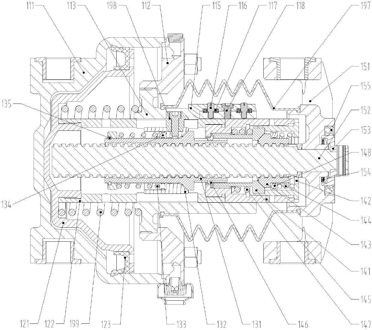
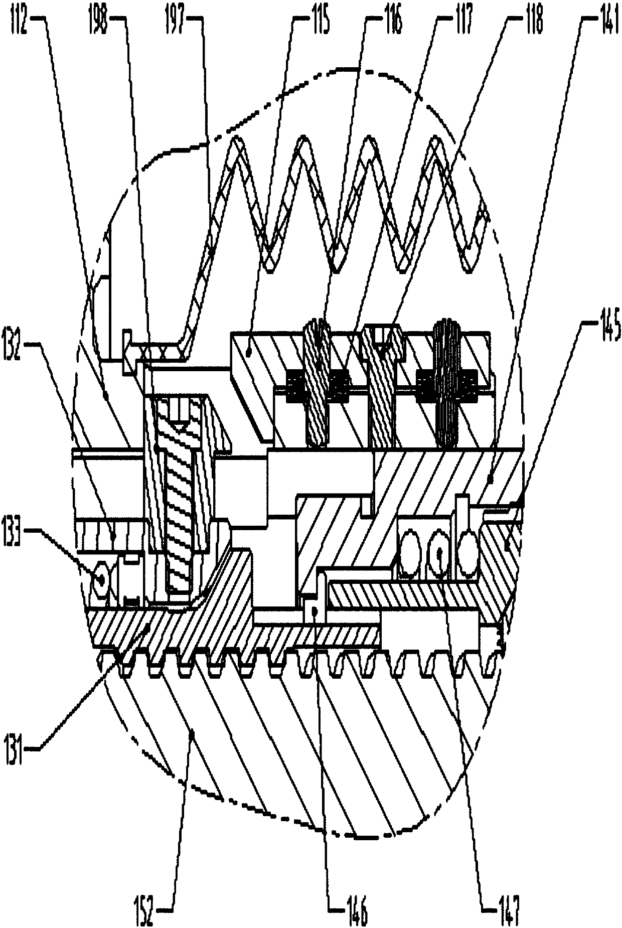
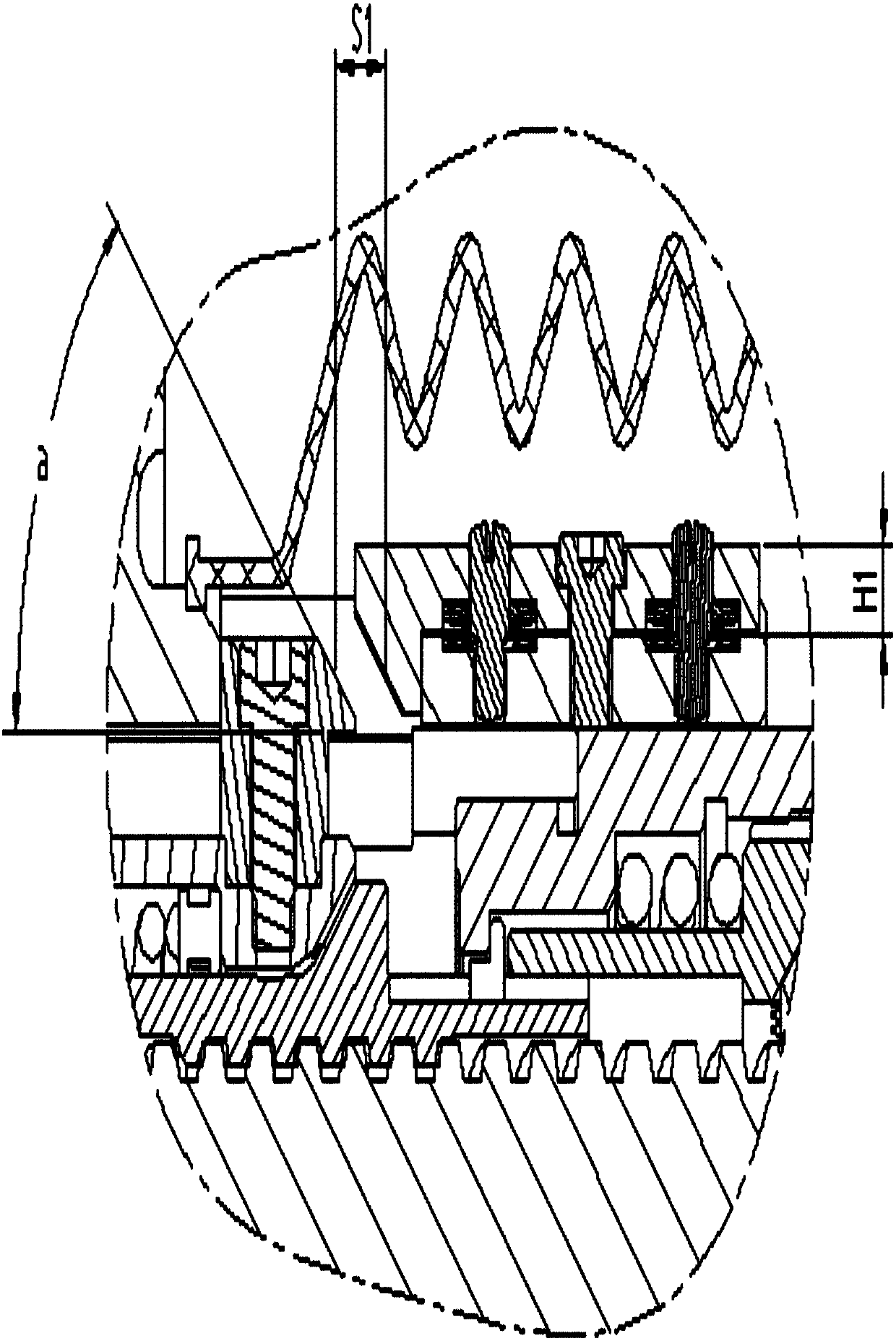
[0055] The basic structure of the brake cylinder gap adjustment mechanism in this embodiment is as follows: figure 1 and figure 2 As shown, it includes a cylinder body 111, a cylinder head 112 and a cylinder head pipe 113 that are fixedly connected to each other. The inner cavity of the cylinder head pipe 113 is nested with a piston pipe 122 that forms an axial movement pair with it. The inner end of the piston pipe 122 is located at the The piston 121 in the cylinder is fixed in the axial direction, and a relief spring 199 is installed between the cylinder head tube 113 and the piston; Have square keyway and wedge-shaped adjusting block 115 installation grooves. A taper sleeve 145 and a guide nut 143 engaged with end faces are installed inside the guide damper body 141 , and the ends of the taper sleeve 145 and the guide nut 143 away from the meshing abut against the damper spring 147 and the guide spring 144 respectively. The inner hole of the guide nut 143 is equipped wi...


PUM


Abstract

The invention relates to a brake cylinder clearance adjusting mechanism and a brake cylinder, and belongs to the technical field of vehicle braking. The brake cylinder clearance adjusting mechanism ischaracterized in that the inner end of a piston tube which is embedded in the inner cavity of a cylinder cover tube is fixedly connected with a piston in the axial direction; the outer end of the piston tube is fixedly connected with a guiding resistance regulator body; a square key groove and a wedge-shaped adjusting block mounting groove are formed in the cylinder cover tube in the axial direction; a taper sleeve and a guiding nut of which the end faces are meshed are mounted in the guiding resistance regulator body; the ends, away from the meshed part, of the taper sleeve and the guiding nut are propped against a resistance regulating spring and a guide spring; an adjusting screw shaft which is screwed in an adjusting nut is mounted in the inner hole of the guiding nut; a tapered toothsliding sleeve is mounted at the outer part of the adjusting nut; the outer circle of the tapered tooth sliding sleeve is fixedly connected with the square key radially extending out of the square key groove in the cylinder cover tube; a wedge-shaped adjusting block adjustable in the radial position is mounted in the wedge-shaped adjusting block mounting groove of the cylinder cover tube; and anouter wedge-shaped surface and an inner wedge-shaped surface are formed in each of the adjacent ends of the square key and the wedge-shaped adjusting block. According to the brake cylinder clearance adjusting mechanism and the brake cylinder, the adjustment of the maximum unadjusted stroke value of the brake cylinder is realized, and a stable clearance adjustment amount is ensured.

Description

technical field [0001] The invention relates to a clearance adjustment mechanism, in particular to a brake cylinder clearance adjustment mechanism and a brake cylinder, belonging to the technical field of vehicle braking. Background technique [0002] As far as the applicant knows, in the current common brake caliper unit structure with clearance adjustment function, the relief clearance in the steady state is usually determined by the maximum non-adjustment stroke of the brake cylinder, which depends on the clearance adjustment mechanism of the brake cylinder related part dimensions. For a long time, the structure of the traditional brake cylinder has determined that the maximum non-adjustable stroke is also determined after the size of the parts is determined, so that the release clearance of the brake caliper in a stable state is a certain value. To change the release clearance, the relevant parts in the brake cylinder clearance adjustment mechanism must be replaced. ...

Claims


Application Information

Patent Timeline
Patent Type & Authority Applications(China)
IPC IPC(8): F16D65/56F16D65/00
CPCF16D65/56F16D65/005F16D65/567F16D65/14F16D2121/04F16D2125/04
Inventor 曾梁彬韩红文王永胜张洪波霍伟雷国伟
Owner CRRC QISHUYAN INSTITUTE CO LTD
Why Eureka
Try Eureka