Banknote identification device

A banknote identification and banknote technology, which is applied in the field of banknote identification devices, can solve the problem of not being able to reach the banknote insertion detection sensor, and achieve the effect of eliminating false detection

Inactive Publication Date: 2018-03-13
FUJI ELECTRIC CO LTD
View PDF3 Cites 1 Cited by
  • Summary
  • Abstract
  • Description
  • Claims
  • Application Information

AI Technical Summary

Problems solved by technology

As a result, the external light incident from the banknote insertion port is repeatedly refle

Method used


Image

  • Banknote identification device
  • Banknote identification device
  • Banknote identification device

Examples


Embodiment Construction

[0028] Hereinafter, modes for implementing the present invention will be described with reference to the drawings.

[0029] (the whole frame)

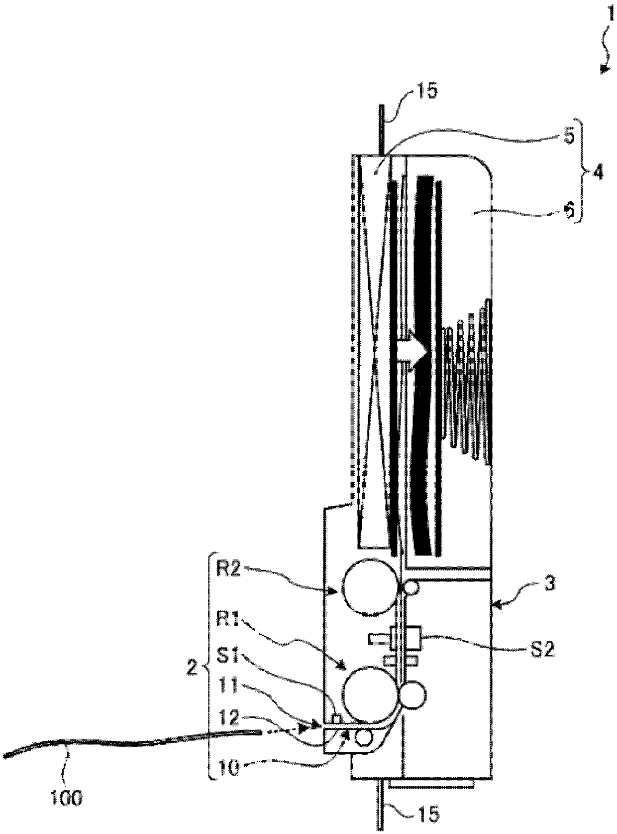
[0030] figure 1 It is a sectional view which shows the structure of the banknote identification apparatus 1 which concerns on embodiment of this invention. Such as figure 1 As shown, the banknote identification device 1 has a conveying unit 2 and an identification unit 3 at the lower part of the device body, and has a banknote storage part 4 at the upper part of the device body.

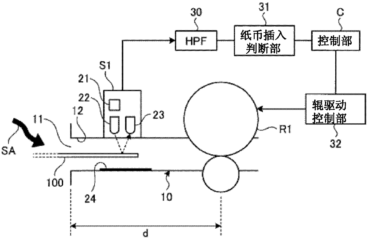
[0031] The conveyance unit 2 has the conveyance path 10 which conveys the banknote 100 from the banknote insertion opening 11 to the banknote accommodating part 4 side via the banknote insertion guide 12, and returns the banknote 100 at the same time. On the conveyance path 10 , reflective sensor S1 , conveyance roller R1 , identification sensor S2 , and conveyance roller R2 are arranged in this order from the banknote insertion port 11 .

[0032] Reflect...


PUM


Abstract

The invention provides a banknote identification device which is simple in structure and can eliminate error detection of banknote inserting which is caused by external light influence coming in froma banknote inserting port. The banknote identification device comprises a reflection sensor (S1), a high pass filter (30) and a banknote inserting part determination part (31). The reflection sensor (S1) is arranged in an inserting guiding member which is used for guiding the banknote which is inserted from the banknote inserting port (11) and is used for transmitting regulated AC signal light andreceiving reflection light. The high pass filter (30) allows a frequency band containing the frequency band of a regulated AC signal light in a receiving signal outputted by the reflection sensor (S1) to pass; the banknote inserting determination part (31) determines whether the banknote (100) is inserted into the banknote inserting guiding member (12) through a receiving signal of the high passfilter (30).

Description

technical field [0001] The present invention relates to a banknote identification device capable of eliminating false detection of banknote insertion due to the influence of external light incident from a banknote insertion opening with a simple structure. Background technique [0002] The banknote recognition apparatus installed in an automatic vending machine etc. has the banknote insertion detection sensor which detects the banknote inserted from the banknote insertion opening. When the banknote insertion detection sensor detects the banknote, the conveying roller is made to rotate in the forward direction to guide the inserted banknote. [0003] However, banknote identification devices installed in automatic vending machines and the like are often placed outdoors, and external light enters from the banknote insertion opening. When the banknote insertion detection sensor is an optical sensor, the banknote insertion may be erroneously detected due to the influence of exte...

Claims


Application Information

Patent Timeline
IPC IPC(8): G07D7/12
CPCG07D7/12
Inventor 田中伸幸
Owner FUJI ELECTRIC CO LTD
Why Eureka
Try Eureka