Refrigerator

A technology for refrigerators and storage rooms, applied in the field of refrigerators, can solve the problems of difficulty in quickly detecting food temperature, complicated control, waste of cooling energy, etc., so as to shorten the continuous operation time, shorten the passing time, and suppress the amount of dripping water. Effect

Inactive Publication Date: 2013-03-06
PANASONIC CORP
View PDF1 Cites 1 Cited by
  • Summary
  • Abstract
  • Description
  • Claims
  • Application Information

AI Technical Summary

Problems solved by technology

Specifically, the conventional switching chamber 9 is set at a freezing temperature, and when the door is opened to confirm only the food 21 stored in the switching chamber 9, the infrared sensor 28 mistakenly detects the temperature at which the food 21 has been put in, and starts cooling. , so the switching chamber 9 will be cooled excessively, and there is a problem that wasteful energy is required
[0016] In addition, in order to solve this problem, there is a method of providing a switch function for detecting the opening and closing of the door, but in the opening and closing of the door, it is necessary to perform interlocking control of the detection of the infrared sensor 28 and the switch control, which causes the complexity of the control, and there is a problem. Factors that may increase malfunctions
[0017] In addition, when water droplets adhere to the front end of the infrared sensor 28 due to condensation or the like, the water droplets are detected without detecting the food 21. Therefore, for example, in order to prevent the detection part of the sensor front end from Condensation also has a method of providing a shutter mechanism in the sensor part of the infrared sensor 28, but it becomes a complicated mechanical structure, which may increase the cause of malfunction
In particular, in the storage room of a low-temperature refrigerator, in such a complicated mechanical structure, problems such as a decrease in the reliability of the mechanical structure and a failure due to a decrease in the lubricity of the lubricating oil are likely to occur. Especially noticeable in rooms with freezing temperatures
In addition, there is a problem that the movement may be hindered due to condensation, freezing, frost, etc.
[0018] In addition, in the other conventional configuration of the above-mentioned Patent Document 2, although it has a certain effect, it is not enough for the market to pay attention to the global environment in recent years, that is, the demand for energy saving and the demand for improvement of the freshness of the refrigerator.
[0019] This kind of problem is also in order to preserve food for a long time while maintaining its freshness. It is important to pass through the temperature range of 0°C to -5°C called the maximum ice crystal formation zone in advance when the food is cooled, and how to suppress cell destruction , as a method for this, quick-freezing control is performed by indirect cooling of cold air, so there is a limit to further accelerating the speed of passing through the maximum ice crystal formation zone of 0°C to -5°C
[0020] In addition, when performing this quick-freezing control, the compressor and the cold air blowing fan are continuously operated to increase the amount of cold air introduced into the freezer compartment 8 to perform quick freezing, so the freezing capacity of the refrigerator can be improved within a certain period of time. The electrical input of the refrigerator is greatly increased. Although the freezing speed is faster than the usual cooling, more energy must be used, and it is not easy to control the quick freezing by saving energy.
[0021] In addition, as described in another conventional example described in Patent Document 2, in the method of directly detecting the temperature of the food by arranging the load temperature sensor 39 at the bottom of the casing 41, which is the container in which the food is placed, during quick freezing, the load The temperature sensor 39 detects the temperature of the housing 41 in contact with the food. It is difficult to quickly detect the temperature of the food itself. The temperature of the food, therefore has the problem of causing a delay in the detection time
[0022] In addition, in addition to food, the load of food stored in the housing 41 other than the food desired to be cooled also requires a corresponding cooling time, so as the quick freezing time, only the actual food 21 is continuously operated, so it will lead to waste of cooling energy

Method used


Image

  • Refrigerator
  • Refrigerator
  • Refrigerator

Examples


Embodiment approach 1

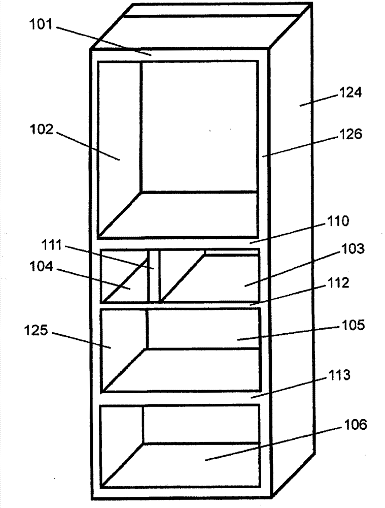
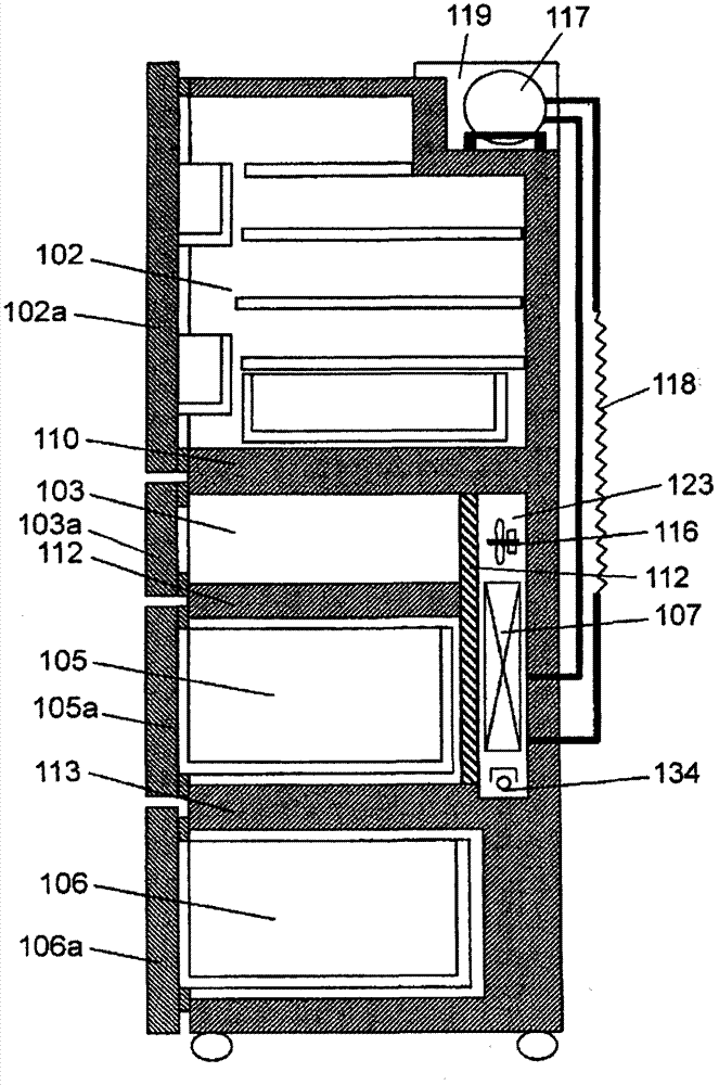
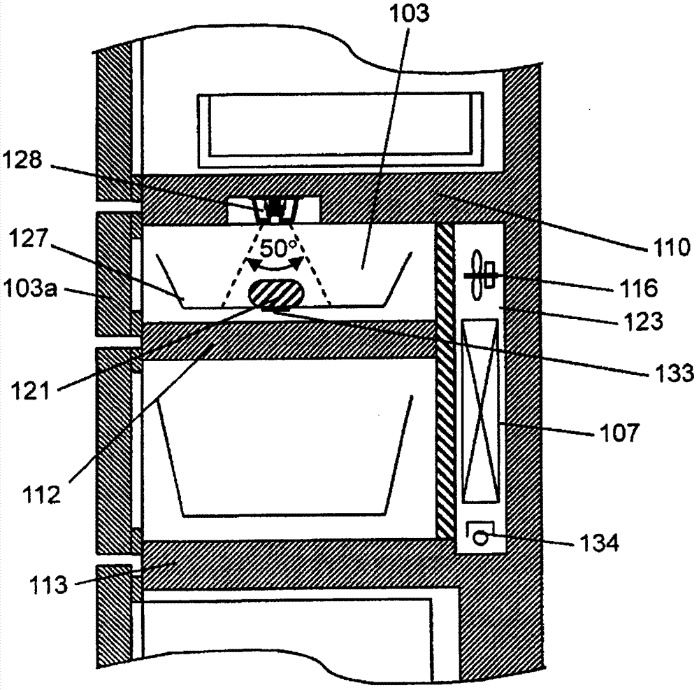
[0091] figure 1 It is a front view of the refrigerator in Embodiment 1 of this invention. figure 2 It is a side sectional view of the refrigerator in Embodiment 1 of this invention. image 3 It is a partially enlarged side sectional view of the upper freezer compartment according to Embodiment 1 of the present invention.

[0092] Such as Figure 1 ~ Figure 3 As shown, the refrigerator main body 101 is made of a metal (for example, iron plate) outer box 124 and a hard resin (for example, ABS) inner box 125 opened to the front, and the outer box 124 and the inner box are filled with foam. The heat insulation box body that polyurethane heat insulation material 126 constitutes between box 125, and is arranged on the refrigerating room 102 of the top of this main body, is arranged on the upper freezer room 103 of the bottom of refrigerating room, in the below of refrigerating room 102 and the upper part. The freezer compartment 103 is composed of an ice-making compartment 104 ...

Embodiment approach 2

[0132] In this embodiment, a detailed description of the same configuration and technical idea as those described in Embodiment 1 will be omitted. Regarding the configuration to which the same technical idea as that described in Embodiment 1 can be applied, a configuration in combination with the technical content and configuration described in Embodiment 1 can be realized.

[0133] Figure 4 It is a partially enlarged side sectional view of the refrigerator according to Embodiment 2 of the present invention. Such as Figure 4 As shown, in the present embodiment, in the configuration of the first embodiment, the surface detected by the infrared sensor 228 installed in the upper freezer compartment 203 is only the container 227, and the third heat-insulating partition located below it is removed. In this Embodiment, the mark 133 is provided also in the place where the infrared sensor 228 of the food mounting surface can detect the temperature with the highest precision.

[0...

Embodiment approach 3

[0137] In the present embodiment, descriptions of parts that have the same configuration or the same technical idea as those described in Embodiment 1 or 2 are omitted. Regarding the configuration to which the same technical idea as that described in Embodiment 1 or 2 can be applied, a configuration that combines the technical content and configuration described in Embodiment 1 or 2 can be realized.

[0138] Figure 5 A partially enlarged side sectional view of a refrigerator according to Embodiment 3 of the present invention. exist Figure 5 Among them, the infrared sensor 328 is installed on the door part of the upper freezer compartment 303, and when the door is opened and closed, the detected temperature and the like are sent to the control part of the refrigerator main body 301 by wireless.

[0139] Thus, even when the door is opened when the food 321 is taken out, the temperature of the food 321 in the casing 327 can be reliably detected, so it is effective for checkin...


PUM


Abstract

There is provided a storage room in which an infrared sensor detecting a surface temperature of a food is installed, and an adjacent storage room which is adjacent on a projection surface of a detection surface of the infrared sensor starting from the infrared sensor, an improvement of precision of a detection temperature at a time of opening and closing a door can be achieved by setting the storage room and the adjacent storage room to the same temperature zone, and a temperature of the food can be stably detected by suppressing a dew condensation and a temperature fluctuation of a thermistor itself which are factors of an erroneous detection.

Description

technical field [0001] The present invention relates to a refrigerator using a non-contact sensor. Background technique [0002] In recent years, as demand for larger refrigerators has increased, refrigerators that have improved volumetric efficiency by reducing dead space and refrigerators that have various layouts from the viewpoint of usability are being sold. [0003] Among them, in refrigerators, in order to detect the temperature in the box, the temperature of the air in the box has been measured with a thermistor. The cooling amount is adjusted by measuring the temperature of the air in the box heated up by the influence of the hot food. However, in such a refrigerator, since the actual temperature of the food is not measured, it is not known whether the food can actually be cooled. Therefore, in order to cool the food, the food is cooled to the target temperature while cooling the surroundings, so there is a problem that it takes time to cool the food itself to the...

Claims


Application Information

Patent Timeline
Patent Type & Authority Patents(China)
IPC IPC(8): F25D29/00F25D11/02
CPCF25D29/00F25D2400/30F25D2700/16
Inventor 堀尾好正田中正昭足立正井下美桃子豆本寿章
Owner PANASONIC CORP
Why Eureka
Try Eureka