Remaining object error detection recognition method and device and image processing equipment

An identification device and error detection technology, applied in the field of image processing, can solve the problems of error detection, residual error detection, etc., and achieve the effect of eliminating error detection

Pending Publication Date: 2020-10-27
FUJITSU LTD
View PDF0 Cites 1 Cited by
  • Summary
  • Abstract
  • Description
  • Claims
  • Application Information

AI Technical Summary

Problems solved by technology

However, real environment changes can lead to false detections, especially in some complex scenes, e.g., if the light keeps changing, false detections of remnants

Method used


Image

  • Remaining object error detection recognition method and device and image processing equipment
  • Remaining object error detection recognition method and device and image processing equipment
  • Remaining object error detection recognition method and device and image processing equipment

Examples


Embodiment 1

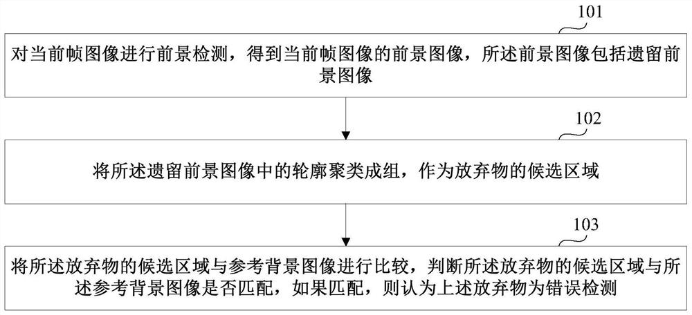
[0038] This embodiment provides an identification method for false detection of remnants, figure 1 It is a schematic diagram of an implementation of the identification method for wrong detection of remnants in Example 1 of the present invention. Please refer to figure 1 , the method includes:

[0039] Step 101: performing foreground detection on the current frame image to obtain a foreground image of the current frame image, the foreground image including the legacy foreground image;

[0040] Step 102: Clustering the contours in the leftover foreground image into groups as candidate regions of the leftovers;

[0041] Step 103: Comparing the candidate area of ​​the leftover with the reference background image, judging whether the candidate area of ​​the leftover matches the reference background image, and if they match, the above-mentioned leftover is considered to be a wrong detection.

[0042] In this embodiment, by comparing the detected candidate area (blob) that is rega...

Embodiment 2

[0088] This embodiment provides an identification device for error detection of remnants. Since the problem-solving principle of this device is similar to the method in Embodiment 1, its specific implementation can refer to the implementation of the method in Embodiment 1. The same content is not Repeat the instructions again.

[0089] Figure 8 It is a schematic diagram of the identification device 800 for wrong detection of remnants in this embodiment, as shown in Figure 8 As shown, the identification device 800 for false detection of remnants includes: a foreground detection unit 801, a clustering unit 802, and a judgment unit 803. The foreground detection unit 801 performs foreground detection on the current frame image to obtain the foreground image of the current frame image, so The foreground image includes a leftover foreground image, the clustering unit 802 clusters the contours in the leftover foreground image into groups as candidate regions of the remnants; the j...

Embodiment 3

[0103] This embodiment provides an image processing device, and the image processing device includes the identification device for false detection of remnants as described in Embodiment 2.

[0104] Figure 10 is a schematic diagram of the image processing apparatus of this embodiment. Such as Figure 10 As shown, the image processing device 1000 may include: a central processing unit (CPU) 1001 and a memory 1002; the memory 1002 is coupled to the central processing unit 1001. The memory 1002 can store various data; in addition, it also stores information processing programs, and executes the programs under the control of the central processing unit 1001 .

[0105] In one embodiment, the function of the identification device 800 for false detection of remnants may be integrated into the central processing unit 1001 . Wherein, the central processing unit 1001 may be configured to implement the identification method for wrong detection of remnants as described in Embodiment 1....


PUM


Abstract

The embodiment of the invention provides a remnant error detection recognition method and device and image processing equipment. The method comprises the steps: carrying out the foreground detection of a current frame image, obtaining a foreground image of the current frame image, and enabling the foreground image to comprise a remnant foreground image; clustering the contours in the remaining foreground image into groups to serve as candidate regions of a remaining object; and comparing the candidate region of the remnant with a reference background image, judging whether the candidate regionof the remnant is matched with the reference background image or not, If so, considering that the remnant is subjected to error detection. A detected candidate region (blob), which is regarded as a remnant, is compared with a cache background (reference background image), If the detected candidate region (blob) matches the cache background (reference background image), the candidate region (blob)is considered not to be a remnant, and it is determined that detection is erroneous. And a judgment result is fed back to the foreground detection module, and corresponding processing is performed through the foreground detection module, so that wrong detection of remnants is eliminated to a certain extent.

Description

technical field [0001] The present invention relates to the technical field of image processing, in particular to an identification method, device and image processing equipment for error detection of remnants. Background technique [0002] In the field of video surveillance, abandoned object detection is the basis for applications such as illegal parking detection, falling object detection, and road intrusion detection. Most algorithms for carryover detection are based on different background modules. The background module is updated based on the historical information of each pixel. Some pixels are judged to be foreground if they are different from the background module. If the foreground remains for a long time, it will be judged as an abandoned region. However, real environment changes can lead to false detections, especially in some complex scenes, e.g., if the light keeps changing, false detections of remnants will occur. [0003] It should be noted that the above ...

Claims


Application Information

Patent Timeline
Patent Type & Authority Applications(China)
IPC IPC(8): G06K9/00G06K9/62G06T7/194
CPCG06T7/194G06T2207/10016G06T2207/20104G06V20/40G06V10/751G06T7/11G06T2207/30232G06V20/54G06V20/52G06V10/255G06V10/267G06V10/759G06F18/217G06F18/232
Inventor 张楠
Owner FUJITSU LTD
Why Eureka
Try Eureka