Electromagnetic induction position detection sensor

a position detection and electromagnetic induction technology, applied in the direction of loop antennas, instruments, electrical/magnetically converting sensor outputs, etc., can solve problems such as erroneous detection, and achieve the effects of reducing the disabled area, and reducing the number of errors

Active Publication Date: 2016-08-09
WACOM CO LTD
View PDF20 Cites 1 Cited by
  • Summary
  • Abstract
  • Description
  • Claims
  • Application Information

AI Technical Summary

Benefits of technology

[0016]A possible approach to solve this problem would be to downsize the disabled area by arranging the loop coils more densely, and moreover downsize an overlapping area OV, for example, by reducing the conductor width of each loop coil, for example, from a normal 100 μm to half or 50 μm. Another possible approach would be to use a multilayer substrate to form the detection sensor. However, these approaches will naturally lead to increased cost.
[0017]In light of the foregoing, it is desirable to achieve an electromagnetic induction position detection sensor capable of accurately detecting the position indicated in the edge portions despite a smaller disabled area and without entailing any major change that would result in increased cost.
[0020]As a result, it is possible to eliminate erroneous detection caused by the relationship between the N-turn loop coil of interest and its adjacent loop coil even if the two-point detection method is used. This prevents erroneous detection of the position indicated by the pen-shaped position indicator in the edge portions of the position detection sensor, thus providing a smaller disabled area and a larger detection area (area where position detection is possible) of the position detection sensor.
[0021]The present invention achieves an electromagnetic induction position detection sensor capable of downsizing the disabled area and upsizing the area where position detection is possible without entailing any major change that would result in increased cost, thus making it possible to deal with so-called slim border intended to reduce the bezel width.

Problems solved by technology

As described earlier, therefore, it is difficult to make an accurate position calculation based on a predetermined relational formula that is dependent on the ratio of the reception signal levels of the loop coils X0 and X1, thus resulting in erroneous detection due to a coordinate jump.

Method used


Image

  • Electromagnetic induction position detection sensor
  • Electromagnetic induction position detection sensor
  • Electromagnetic induction position detection sensor

Examples


modification examples

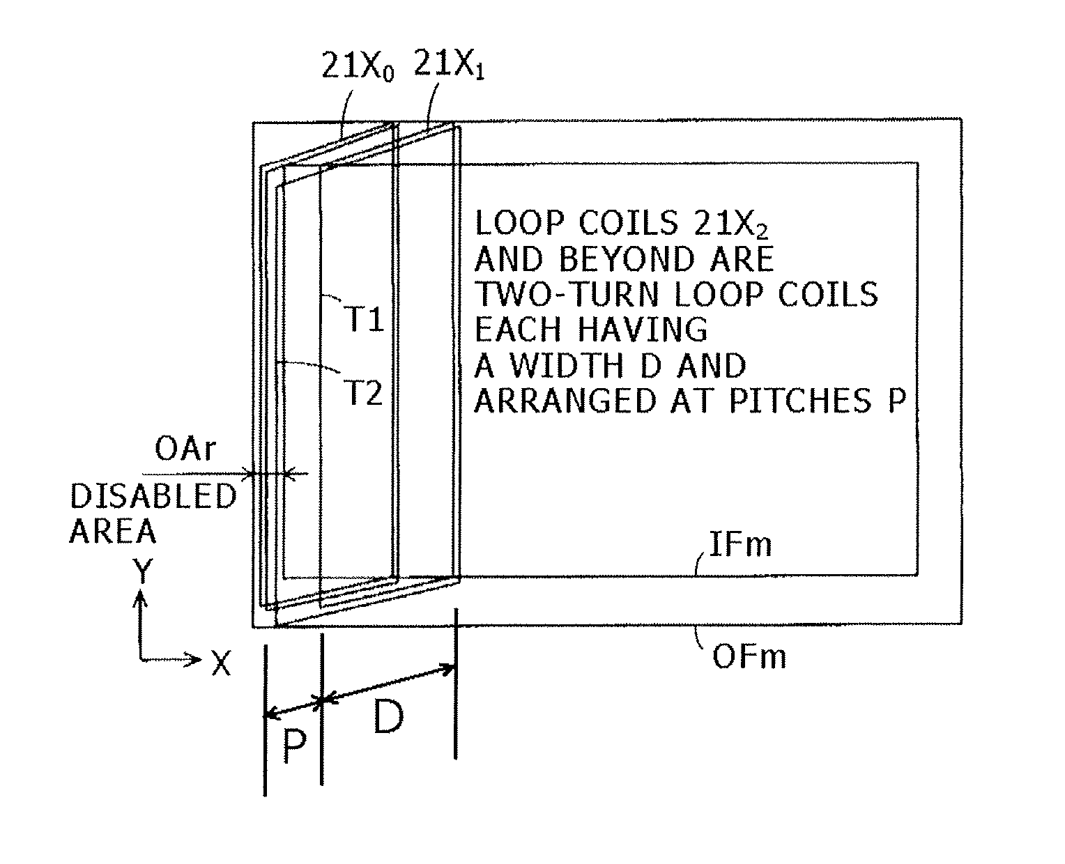
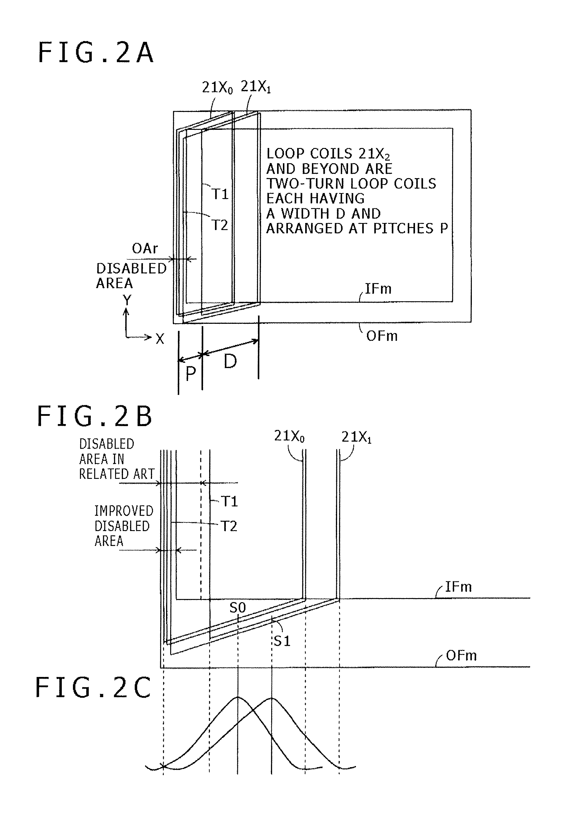
[0090]Although a description has been given, in the embodiment described above, of a case in which the present invention is applied to the second loop coil 21X1 from the left edge in the sensor section 20, the present invention is not limited thereto. Instead, the present invention is applicable to the third, fourth or other loop coil at an appropriate position from one of the edges of the sensor section to which the present invention is applied. It is only necessary to determine to which loop coil the present invention is to be applied based on tradeoffs with the reception signal distributions of the loop coils.

[0091]Further, a description has been given assuming that loop coils having a given number of turns such as two turns make up the X-axis direction loop coil group 21 and Y-axis direction loop coil group 22 of the sensor section 20 according to the present embodiment. However, the present invention is not limited thereto. Instead, it is only necessary to use a loop coil havin...


PUM


Abstract

An electromagnetic induction position detection sensor includes a plurality of loop coils, each being an N-turn loop coil formed by winding a conductor N times (N is an integer equal to or greater than 2), and each coil turn having long side portions that are separated by a predetermined width and that are parallel to each other. The loop coils are arranged at predetermined intervals in a predetermined direction intersecting the long side portions of the loop coils. The width of at least one of the N turns of the Mth loop coil from the edge portion of the sensor in the predetermined direction (M is an integer equal to or greater than 2) is larger than the predetermined width, with the long side portion of this turn of the Mth loop coil arranged more outward than the long side portions of the other turns of the Mth loop coil.

Description

CROSS-REFERENCE TO RELATED APPLICATION[0001]The present application claims priority under 35 U.S.C. 119(a) to Japanese Patent Application No. 2012-214345, filed Sep. 27, 2012, which is incorporated by reference herein.BACKGROUND[0002]1. Technical Field[0003]The present invention relates to an indicated position detection sensor of an electromagnetic induction indicator position detector used as an input device of electronic equipment such as tablet terminal.[0004]2. Description of the Related Art[0005]Recent years have seen the use of electromagnetic induction position input devices as input devices for tablet terminals and intelligent mobile phone terminals called smartphones. These position input devices each include a position indicator and indicator position detector. The position indicator is in the shape of a pen (pen-shaped position indicator). The indicator position detector has an input surface, on which pointing operation is performed, and text, graphics and other informat...

Claims


Application Information

Patent Timeline
Patent Type & Authority Patents(United States)
IPC IPC(8): G01B7/14G01D5/20G06F3/046H01Q7/00
CPCG06F3/046H01Q7/00G01D5/2073G06F3/033
Inventor KOBORI, TAKESHI
Owner WACOM CO LTD
Why Eureka
Try Eureka