superstructure

A car body and vehicle technology, applied in the direction of upper structure, upper structure sub-assembly, vehicle parts, etc., can solve the problems of increasing weight, increasing cost, increasing car body weight, etc., to improve connection strength, suppress deformation, and suppress torsion deformation effect

Active Publication Date: 2021-04-13
SUZUKI MOTOR CORP
View PDF7 Cites 0 Cited by
  • Summary
  • Abstract
  • Description
  • Claims
  • Application Information

AI Technical Summary

Problems solved by technology

This leads to the problem of increasing the weight of the vehicle body
In addition, the use of reinforcing pipes leads to the problem of not only increasing the weight but also increasing the cost

Method used


Image

  • superstructure
  • superstructure
  • superstructure

Examples


no. 1 approach

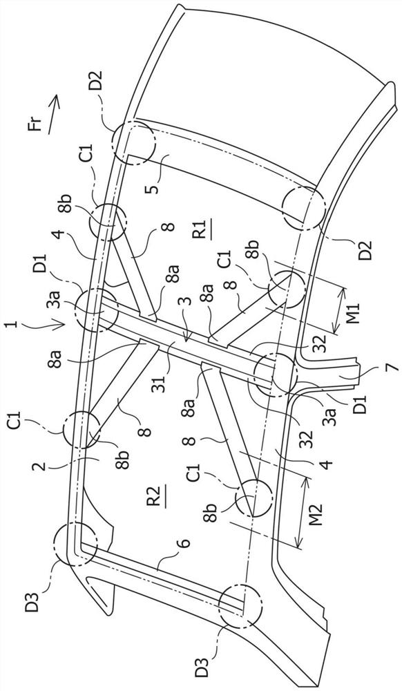
[0024] figure 1 A vehicle body superstructure according to a first embodiment of the present invention is shown.

[0025] like figure 1 As shown, the vehicle body upper part 1 of the vehicle to which the structure according to the first embodiment of the present invention is applied mainly includes a resin roof 2, a roof cross member 3 extending in the vehicle width direction, a Roof rails 4 extending on the left and right sides of the vehicle body, and roof front rails 5 and roof rear rails 6 extending in the vehicle width direction at front and rear end portions of the vehicle body, respectively. The resin roof 2 is a resin plate or the like for reducing the weight of the vehicle body. The resin roof 2 is the peripheral parts of the roof rails 4 located on the left and right sides of the vehicle body upper part 1 and the roof front beams 5 and roof rear beams 6 respectively located at the front and rear end parts of the vehicle body upper part 1, and the resin vehicle The...

no. 2 approach

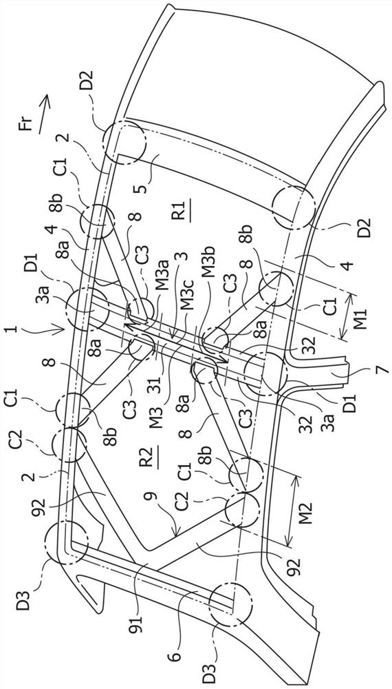
[0035] figure 2 A vehicle body superstructure according to a second embodiment of the present invention is shown. The same parts as those explained in the above-mentioned first embodiment are denoted by the same reference numerals, and repeated description thereof is omitted.

[0036] In the vehicle body upper part 1 according to the second embodiment, in addition to the structure according to the first embodiment, as figure 2 As shown, a second reinforcing member 9 is arranged in the vehicle rear side region R2 to connect the roof rear rail 6 to the respective roof rails 4 located on the left and right sides. The second reinforcement member 9 includes: a beam joint portion 91 at which the second reinforcement member 9 is joined to the roof rear rail 6 ; and a side member joint portion 92 at which the second reinforcement member 9 is branched. While extending toward the front of the vehicle along the oblique direction and extending to a corresponding one of the roof rails ...

no. 3 approach

[0039] figure 1 A vehicle body superstructure according to a third embodiment of the present invention is shown. The same parts as those explained in the above-mentioned first embodiment are denoted by the same reference numerals, and repeated description thereof is omitted.

[0040] In the vehicle front side region R1 of the vehicle body upper portion 1 according to the third embodiment, in addition to the structure according to the first embodiment, as figure 1 As shown, the connection portion C1 between the roof rail 4 and the first reinforcement member 8 is arranged in the middle area in the thirdly divided area in the vehicle front-rear direction between the roof rail 3 and the roof front rail 5 . M1. Furthermore, in the vehicle rear side region R2 of the vehicle body upper portion 1 , the connecting portion C1 between the roof rail 4 and the first reinforcement member 8 is arranged such that the connecting portion C1 is located between the roof rail 3 and the roof rear...


PUM


Abstract

To provide a vehicle body upper structure, the purpose of which is to reduce the weight of the vehicle body and improve the torsional rigidity and side impact performance of the vehicle body. The upper structure of the car body includes: a roof (2); a roof beam (3), which extends along the width direction of the vehicle; and roof rails (4) located on the left and right sides, which extend along the Extending in the front-to-rear direction, the roof cross member (3) and the roof rail (4) are connected to each other by first reinforcement members (8), each first reinforcement member (8) being arranged from the vehicle width of the roof cross member (3) to The middle part of the direction extends to a corresponding one of the roof rails (4) located on the left and right sides along the inclined direction, and each first reinforcement member (8) is arranged on the roof rail ( 3) in the vehicle front side region (R1) or the vehicle rear side region (R2).

Description

technical field [0001] The invention relates to the superstructure of a vehicle body. Background technique [0002] Conventionally, a technique for reducing the weight of a vehicle body by molding a roof at the upper portion of the vehicle body using a resin material is known. Generally, the roof of the upper part of the vehicle body greatly contributes to the torsional rigidity of the vehicle body and the performance of the vehicle body at the time of side collision. In addition, plates made of resin materials have poor mechanical properties compared to steel plates. Therefore, in a vehicle using a resin roof, the torsional rigidity of the vehicle body and the performance of the vehicle body at the time of a side collision deteriorate. [0003] Also, as means for reducing the weight of the vehicle body, a technique for reducing the weight of the vehicle body by reducing the thickness of the steel plate used for the roof of the upper portion of the vehicle body is known. ...

Claims


Application Information

Patent Timeline
Patent Type & Authority Patents(China)
IPC IPC(8): B62D25/06
CPCB62D25/06
Inventor 村瀬祐大长岛洋明
Owner SUZUKI MOTOR CORP
Why Eureka
Try Eureka