
Automatic rotating die-cutting machine

A die-cutting machine and die-cutting technology, applied in the directions of sending objects, thin material handling, transportation and packaging, etc., can solve the problems of poor automation performance of die-cutting machines and poor consistency of die-cutting products.

Pending Publication Date: 2018-03-16
SHENZHEN HADESHENG PRECISION TECH
View PDF0 Cites 1 Cited by
  • Summary
  • Abstract
  • Description
  • Claims
  • Application Information

AI Technical Summary

Problems solved by technology

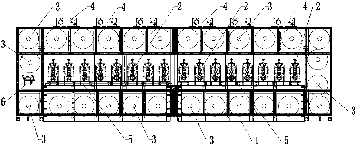
[0004] The technical purpose of the present invention is to overcome the technical problems of poor automation performance and poor consistency of die-cut products in the prior art, and to provide a high-efficiency die-cut product that can simultaneously perform multiple station products and has consistent products. Excellent automatic rotary die-cutting machine

Method used


Image

  • Automatic rotating die-cutting machine
  • Automatic rotating die-cutting machine

Examples


Embodiment Construction

[0018] In order to make the purpose, technical solutions and advantages of the embodiments of the present invention clearer, the technical solutions in the embodiments of the present invention will be clearly and completely described below in conjunction with the drawings in the embodiments of the present invention. Obviously, the described embodiments It is a part of embodiments of the present invention, but not all embodiments. The components of the embodiments of the invention generally described and illustrated in the figures herein may be arranged and designed in a variety of different configurations. Accordingly, the following detailed description of the embodiments of the invention provided in the accompanying drawings is not intended to limit the scope of the claimed invention, but merely represents selected embodiments of the invention. Based on the embodiments of the present invention, all other embodiments obtained by persons of ordinary skill in the art without cre...


PUM


Abstract

The invention discloses an automatic rotating die-cutting machine. The automatic rotating die-cutting machine comprises a mounting rack; a plurality of die-cutting stations are sequentially mounted onthe mounting rack; a plurality of winding and unwinding shafts are sequentially disposed on the mounting rack around the die-cutting stations; each winding and unwinding shaft is driven through a motor to rotate; an automatic deviation rectification device which rectifies deviation of the die-cutting process is further disposed at one end of the mounting rack; die-cutting cutters are connected with die-cutting motors; the die-cutting motors are connected with a control switch; and upper auxiliary shafts used for material winding and unwinding are mounted on the upper portion of the mounting rack. Unwinding and winding are driven through the motors, and then the whole unwinding and winding action is finished; the die-cutting stations are disposed in the middle, the die-cutting cutters on the die-cutting stations are cylindrical die-cutting cutters, and die-cutting of different products is achieved by replacing the die-cutting cutters on the different die-cutting stations; and the automatic deviation rectification device is used for calibrating the unwinding process during material unwinding, so that reject products caused by material deviation are avoided and then the ratio of qualified products is increased.

Description

technical field [0001] The invention relates to a mechanical tooling in the field of die-cutting, more specifically, to an automatic rotary die-cutting machine. Background technique [0002] In the prior art, there are technical defects such as low operation and production efficiency and poor product consistency for the semi-automatic cross-cutting machine of mobile phone film or computer protective film and double-sided self-adhesive in the printing industry. The improvement of human resources cost and the cost increase caused by the poor consistency of die-cut products in the prior art die-cutting machines have become technical problems urgently to be solved by those skilled in the art. [0003] In order to cope with different die-cutting products, sometimes multiple stations are needed to meet the die-cutting requirements; in the prior art, three or four stations can generally meet the requirements, so most die-cutting machines are three or four stations However, sometim...

Claims


Application Information

Patent Timeline
IPC IPC(8): B65H35/06
CPCB65H35/06B65H2301/41398
Inventor 文莲霍灿广张占平李建国吕正君姜军权
Owner SHENZHEN HADESHENG PRECISION TECH
Learn More