Pre-buried warhead fuze chamber and charging method

A warhead and fuze technology, which is applied in the directions of ammunition, offensive equipment, weapon accessories, etc., can solve the problems of increasing detonation distance, affecting the reliability of detonation, and unstable fixation, and achieves high safety and stable detonation distance. The effect of controllable and guaranteed charge quality

Active Publication Date: 2019-06-28
湖北三江航天红林探控有限公司
View PDF3 Cites 0 Cited by
  • Summary
  • Abstract
  • Description
  • Claims
  • Application Information

AI Technical Summary

Problems solved by technology

This method also has the disadvantage that it is easy to bring in air when inserting the core, and it is not firm to fix the fuze chamber on the mandrel by bonding. After the charge is solidified and cooled, the position of the fuze chamber is prone to subsidence as the charge shrinks. It may cause the detonation transmission distance between the fuze, the detonation booster column and the main charge to be too long, which will affect the detonation transmission reliability

Method used


Image

  • Pre-buried warhead fuze chamber and charging method
  • Pre-buried warhead fuze chamber and charging method
  • Pre-buried warhead fuze chamber and charging method

Examples


Embodiment 1

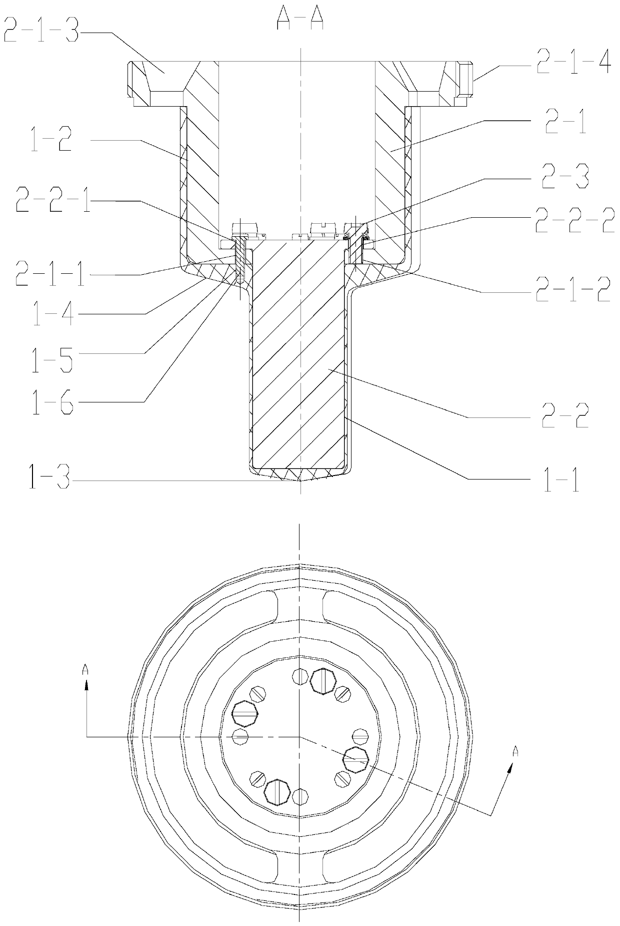
[0062] Embodiment 1: when the charge inner chamber 1-8 surface of the warhead 1-7 projectile contains thread 2-1-4a

[0063] Such as Figure 6 As shown, the embedded warhead fuze chamber 1 is set on the positioning device 2 coated with anti-sticking coating, and connected and fixed by connecting screws 1-6. Before pouring the charge, the thread 2-1-4a on the step circumference of the upper mandrel 2-1 is matched with the thread above the charge surface of the warhead 1-7 body cavity, so that the pre-buried warhead fuze chamber 1 Locate at the specified position of the charge inner cavity 1-8, and then install the protective gear 1-10 above the end surface of the positioning device 2 in the body cavity, so as to prevent the slurry from polluting the thread of the body cavity during the charging process. 1. A protective cover 1-9 is installed on the upper end surface. The protective cover 1-9 can be made of rubber, polytetrafluoroethylene and other materials, and is fixed on th...

Embodiment 2

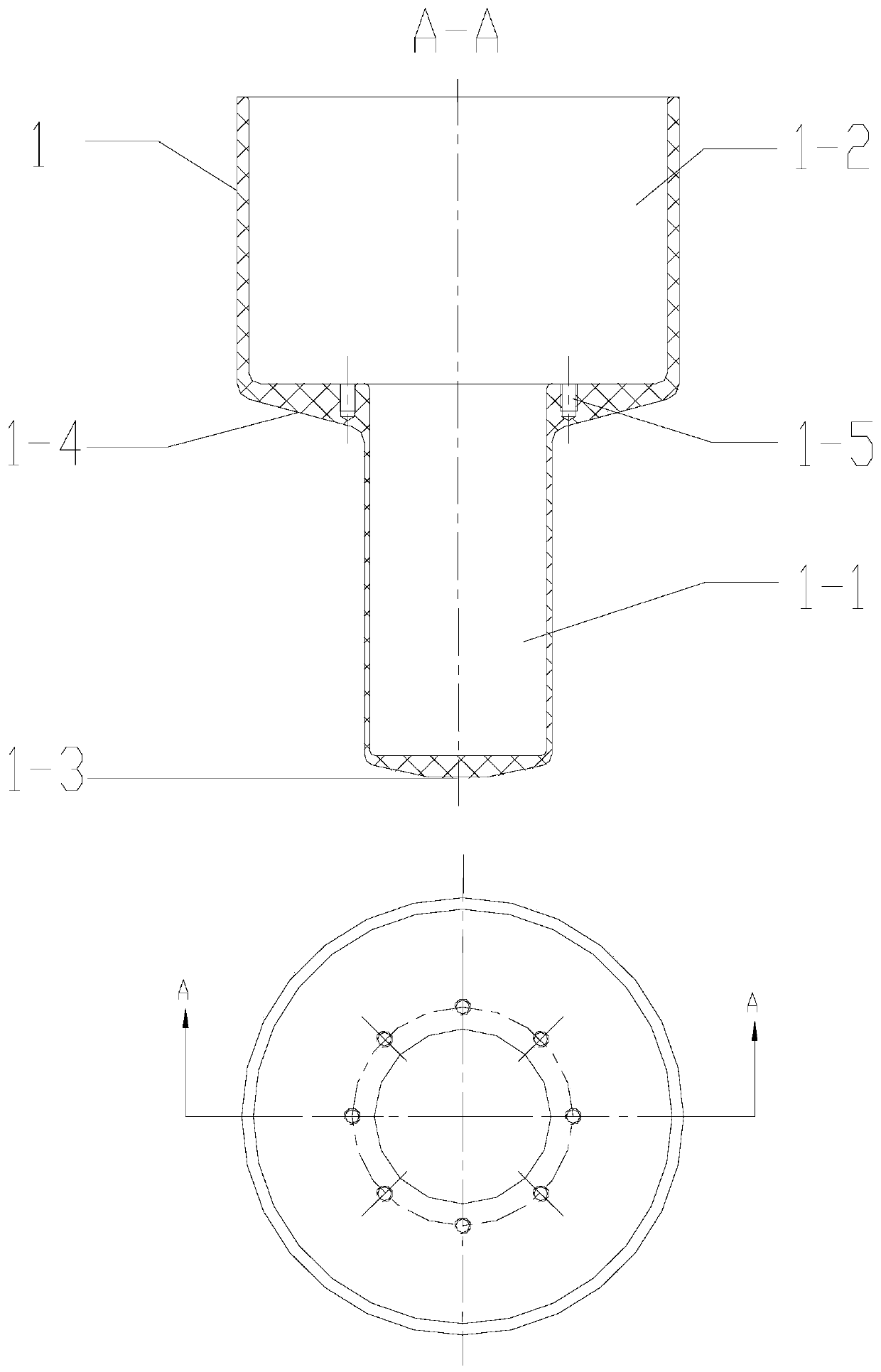
[0064] Embodiment 2: The inner cavity of the warhead 1-7 shell contains a closure above the charge surface

[0065] Such as Figure 7 As shown, the embedded warhead fuze chamber 1 is set on the positioning device 2 coated with anti-sticking coating, and connected and fixed by connecting screws 1-6. Before pouring the charge, the positioning platform 2-1-4b on the step circumference of the upper mandrel 2-1 cooperates with the closing end face of the warhead 1-7 projectile, so as to position the pre-buried warhead fuze chamber 1 in the charge Cavity 1-8 specifies the position, and then installs the protective cover 1-9 on the upper surface of the upper mandrel 2-1. The protective cover 1-9 can be made of rubber, polytetrafluoroethylene and other materials, and is clamped with the upper mandrel 2-1 It is fixed on the end face of the upper mandrel 2-1 by means of cooperation or threaded connection to prevent the slurry from entering the cavity of the upper mandrel 2-1, and final...

Embodiment 3

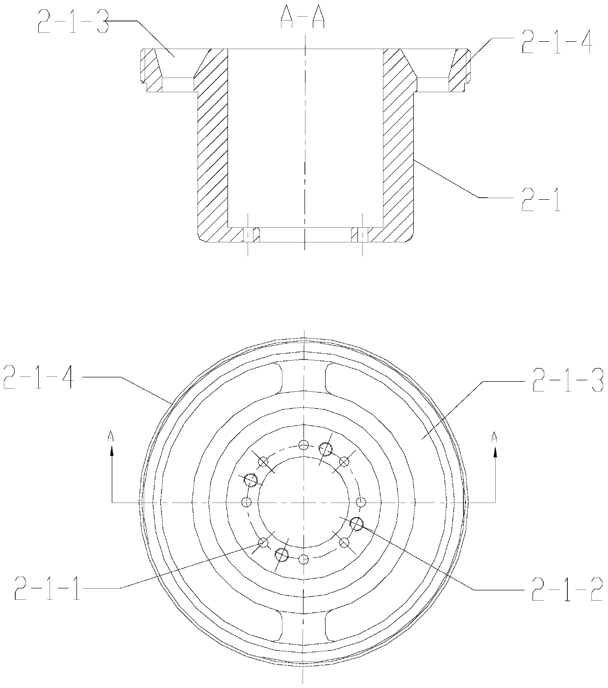
[0066] Embodiment 3: There is no thread 2-1-4a or closing above the charge surface of the warhead 1-7 body cavity

[0067] Such as Figure 8 As shown, the embedded warhead fuze chamber 1 is set on the positioning device 2 coated with anti-sticking coating, and connected and fixed by connecting screws 1-6. Before pouring the charge, the positioning platform 2-1-4b on the step circumference of the upper mandrel 2-1 cooperates with the rear end surface of the warhead 1-7 projectile, so as to position the pre-buried warhead fuze chamber 1 in the charge Cavity 1-8 specifies the position, and then installs the protective cover 1-9 on the upper surface of the upper mandrel 2-1. The protective cover 1-9 can be made of rubber, polytetrafluoroethylene and other materials, and is clamped with the upper mandrel 2-1 It is fixed on the end face of the upper mandrel 2-1 by means of cooperation or threaded connection to prevent the slurry from entering the cavity of the upper mandrel 2-1, an...


PUM


Abstract

The invention discloses an embedded type payload fuze chamber, a positioning device of the embedded type payload fuze chamber and an explosive loading method. The embedded type payload fuze chamber comprises a fuze mounting cavity and an explosive lead mounting cavity; the positioning device comprises an upper mandrel and a lower mandrel; a positioning connector and at least one discharge port areformed in the upper mandrel; a first connecting hole and a second connecting hole are formed in the upper edge of the lower mandrel; the upper mandrel and the lower mandrel are connected through tightening screws for forming the positioning device to be nested into the fuze cavity; and the fuze cavity is positioned in an inner cavity of a payload to be loaded with an explosive through the positioning connector of the upper mandrel. Through the technical scheme, the production efficiency and safety are improved effectively, an explosive loading technology is simplified substantially; the situation that a fuze successfully detonates an explosive lead and then detonates a main charge is guaranteed, and the explosive loading invariability is improved.

Description

technical field [0001] The invention relates to the technical field of warhead charge, is especially suitable for pouring PBX charge, and provides a pre-buried warhead fuze chamber and a warhead charge method. Background technique [0002] With the improvement of the safety requirements of the missile weapon system, a large number of insensitive agents are used for the main charge of the warhead. The column and the part of the fuze outputting detonation energy are pre-buried in the main charge of the warhead. Under this design, it is necessary to ensure that the relative positions of the fuze, the booster column, and the main charge are stable, so as to prevent the shrinkage of the main charge from causing the excessive expansion of the transmission distance between the fuze, the booster column, and the main charge. , to ensure stable and reliable detonation energy transfer of the detonation series. For the anti-hard target warhead, it is also necessary to effectively prev...

Claims


Application Information

Patent Timeline
Patent Type & Authority Patents(China)
IPC IPC(8): F42B33/02
CPCF42B33/02F42B33/0278
Inventor 徐继能王晓晨孙葵
Owner 湖北三江航天红林探控有限公司
Why Eureka
Try Eureka