
CT equipment, reference detector and ray detection method for ray source

A technology of reference detection and ray source, which is applied in measuring devices, instruments for radiological diagnosis, radiation measurement, etc., can solve problems such as image artifacts, facilitate diagnosis, avoid artifacts, and improve image quality Effect

Active Publication Date: 2018-03-20
SHANGHAI UNITED IMAGING HEALTHCARE
View PDF4 Cites 10 Cited by
  • Summary
  • Abstract
  • Description
  • Claims
  • Application Information

AI Technical Summary

Problems solved by technology

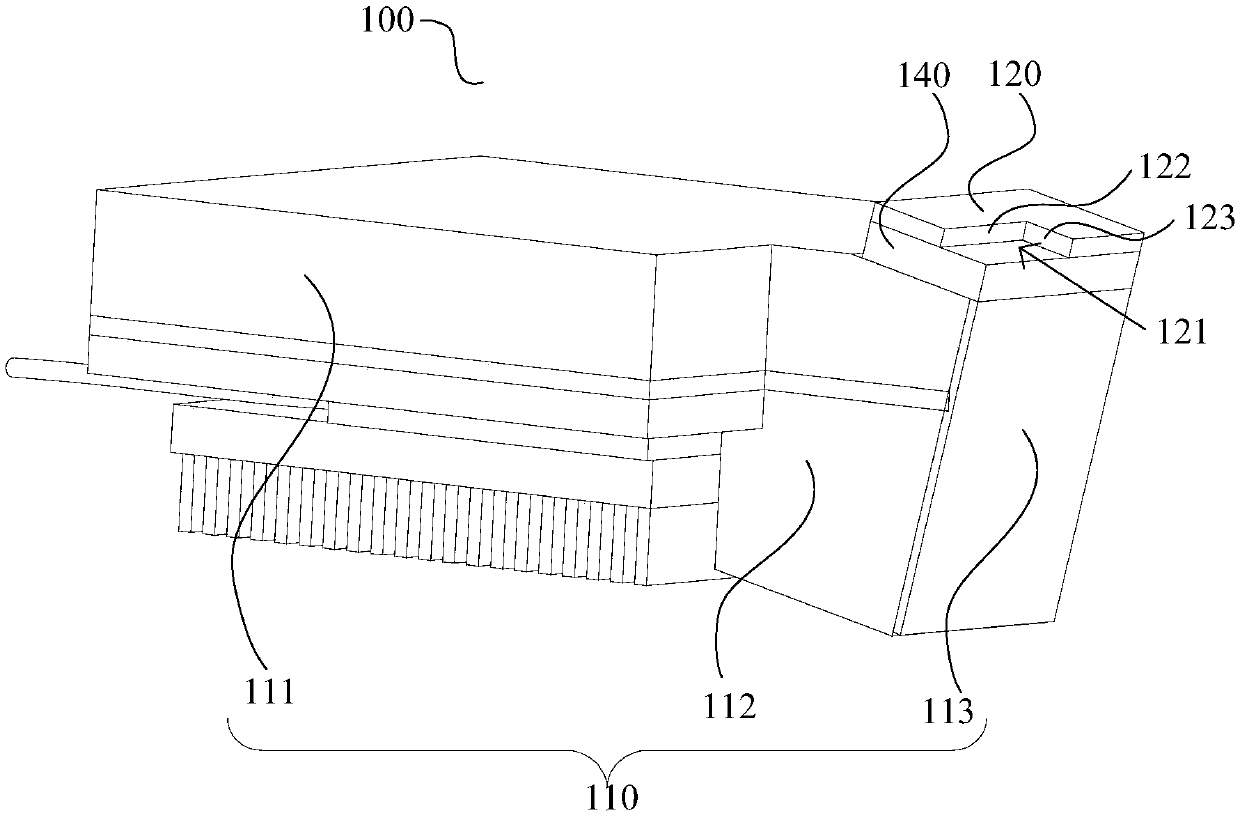
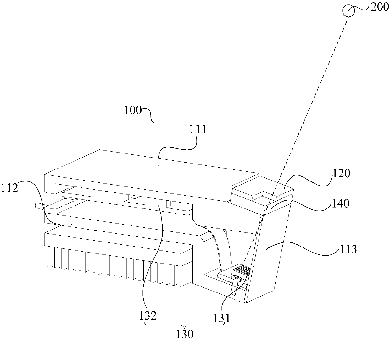
[0003] Based on this, it is necessary to provide a reference for tracking the focus position and ray intensity of the tube to avoid image artifacts in order to solve the current problem of image artifacts caused by X-ray output fluctuations caused by tube position offset. The detection device also provides a radiation detection method for a radiation source, and provides a CT device containing the above-mentioned reference detection device

Method used


Image

  • CT equipment, reference detector and ray detection method for ray source
  • CT equipment, reference detector and ray detection method for ray source
  • CT equipment, reference detector and ray detection method for ray source

Examples


Embodiment Construction

[0052] In order to make the purpose, technical solution and advantages of the present invention clearer, the CT equipment, the reference detection device and the radiation detection method of the radiation source of the present invention will be further described in detail through the following embodiments and in conjunction with the accompanying drawings. It should be understood that the specific embodiments described here are only used to explain the present invention, not to limit the present invention.

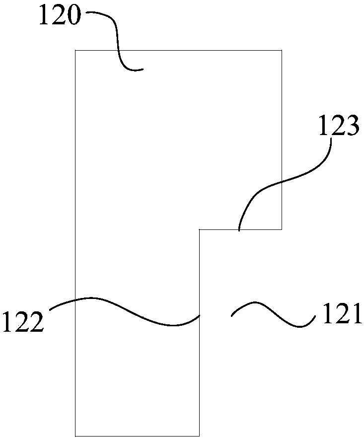
[0053] see Figure 1 to Figure 3, the present invention provides a reference detection device 100, and the reference detection device 100 is set in a scanning system. In this embodiment, the scanning system is described by taking CT equipment as an example. The CT equipment includes a radiation source, a reference detection device 100 and an imaging detection device. The radiation source refers to the tube 200 in this embodiment. The imaging detection device is used to re...


PUM


Abstract

The invention provides a reference detector. The reference detector is provided with an incident window used for enabling the rays to pass, the reference detector also comprises a detection component,and the rays are arranged in the incident window in a penetrating manner and are projected onto the detection component; the detection component determines a focal position of a ray source accordingto ray energy information detected in a projection region of the rays projected onto the detection component; and / or determines ray intensity of the ray source according to the ray energy informationdetected in a preset region of the detection component, wherein the incident window is provided with at least two edges extending along different directions so as to limit the projection region and / orthe preset region. Therefore, the focal position of the ray source can be tracked and the ray intensity of the ray source can be detected, and further imaging of a CT system is corrected, so that anartifact is avoided from appearing during image imaging due to ray output fluctuation, and image imaging quality is improved. The invention also provides CT equipment and a ray detection method for the ray source.

Description

technical field [0001] The invention relates to the technical field of medical equipment, in particular to a radiation detection method for CT equipment, a reference detection device and a radiation source. Background technique [0002] At present, imaging equipment such as a CT machine usually emits X-rays to scan the human body through a ball tube, and receives and detects the X-rays through a detector. However, during the scanning process of imaging equipment such as CT machines, the position of the tube will be shifted due to factors such as temperature, which will cause fluctuations in the output of X-rays, resulting in changes in the intensity of X-rays and the position of the focal point. If the original X-ray intensity and focus position data emitted by the tube are still used in image reconstruction, image artifacts will be caused, resulting in poor image quality, which is not conducive to the doctor's diagnosis. Contents of the invention [0003] Based on this, ...

Claims


Application Information

Patent Timeline
IPC IPC(8): A61B6/03A61B6/00G01T1/161
CPCA61B6/035A61B6/40A61B6/5258A61B6/58G01T1/161
Inventor 叶婷杜岩峰
Owner SHANGHAI UNITED IMAGING HEALTHCARE
Learn More