Tomographic scanning X-ray inspection system using transmitted and compton scattered radiation

a technology of tomographic scanning and x-ray inspection, which is applied in the direction of material analysis using wave/particle radiation, x/gamma/cosmic radiation measurement, instruments, etc., can solve the problems of inability to count individual x-rays, high x-ray rate on scintillators, etc., to avoid artifacts in low z images, improve photon collection efficiency, and avoid high z images

Inactive Publication Date: 2005-04-28
CONTROL SCREENING
View PDF52 Cites 40 Cited by
  • Summary
  • Abstract
  • Description
  • Claims
  • Application Information

AI Technical Summary

Benefits of technology

[0012] Preferably, the images produced by the transmission detector and backscatter detector are displayed as adjacent windows of the same monitor. Signal information from the transmission detector is used to correct for attenuation effects in the backscatter images, thereby avoiding artifacts in the low Z images produced by attenuation due to high Z objects. Conversely, signal information from the backscatter detectors can be used to correct for scatter effects in the transmission image, thereby avoiding artifacts in the high Z image produced by scattering attenuation due to low Z objects. By means of these corrections a greater fraction of the image on the high Z window display is derived from absorption effects of high Z objects, and a greater fraction of the image on the low Z window display is derived from scattering effects of low Z objects. Accordingly, the images displayed by the high Z and low Z windows are more distinct.
[0013] Tomographic information can optionally be obtained by using additional Compton backscatter detectors. Backscattered X-rays originating from elements close to the bottom of the object hit mainly the scintillator next to the entrance slit, while backscatter from elements further up the pencil beam hit all backscatter scintillation detectors nearly equally. Photon collection efficiency is improved and real-time image noise is reduced, when compared to collimation methods that limit angular admittance of photons. The tomographic zones can be displayed in windowed sections on a single monitor or on separate monitors.
[0014] In some embodiments of the invention, dual energy information is optionally obtained with the transmission detection system. Such information can be obtained, for example, by using at least one additional detector overlaying the extant transmission detector. Alternatively, the output of the transmission detector can be analyzed, e.g. by pulse height analysis, to divide the detected transmission signal into low energy and high energy components. This information can be displayed as a dual energy image, which is color coded to designate the atomic number of an object under inspection. A single energy image yields only object radiographic density information, as contrasted to a dual energy image, which yields radiographic density and atomic number, Z, of the object under inspection. Combining the information from the backscatter data and dual energy data can further enhance discrimination of different materials and aid in the separation of overlaying materials of different atomic number Z.
[0015] By employing relatively fast scintillators for faster X-ray detection efficiency, the present invention significantly improves image resolution. Detector design is improved by the use of optically adiabatic scintillators. The system switches between photon-counting and photon integration modes to reduce noise and significantly increase overall image quality. In addition, the system automatically adjusts belt speed (i) to allow rapid entrance into the inspection zone, (ii) slow traverse through the inspection zone to prolong residence therein of articles appointed for inspection, and (iii) allow rapid exit from the inspection zone. This automatic belt speed adjustment feature affords increased resolution and reduced noise with minimum speed penalty. Advantageously, the system provides a sharper and more quickly acquired image that affords improved capability for recognizing bombs, firearms and other weapons, currency, narcotics, incendiary materials, agents that pose biological, chemical, or radiological danger, and other contraband shapes and accompaniments.

Problems solved by technology

In the case where there is no object or a very weak absorbing object the X-ray rate on the scintillator can be so high that counting individual X-rays is not possible.

Method used


Image

  • Tomographic scanning X-ray inspection system using transmitted and compton scattered radiation
  • Tomographic scanning X-ray inspection system using transmitted and compton scattered radiation
  • Tomographic scanning X-ray inspection system using transmitted and compton scattered radiation

Examples


Embodiment Construction

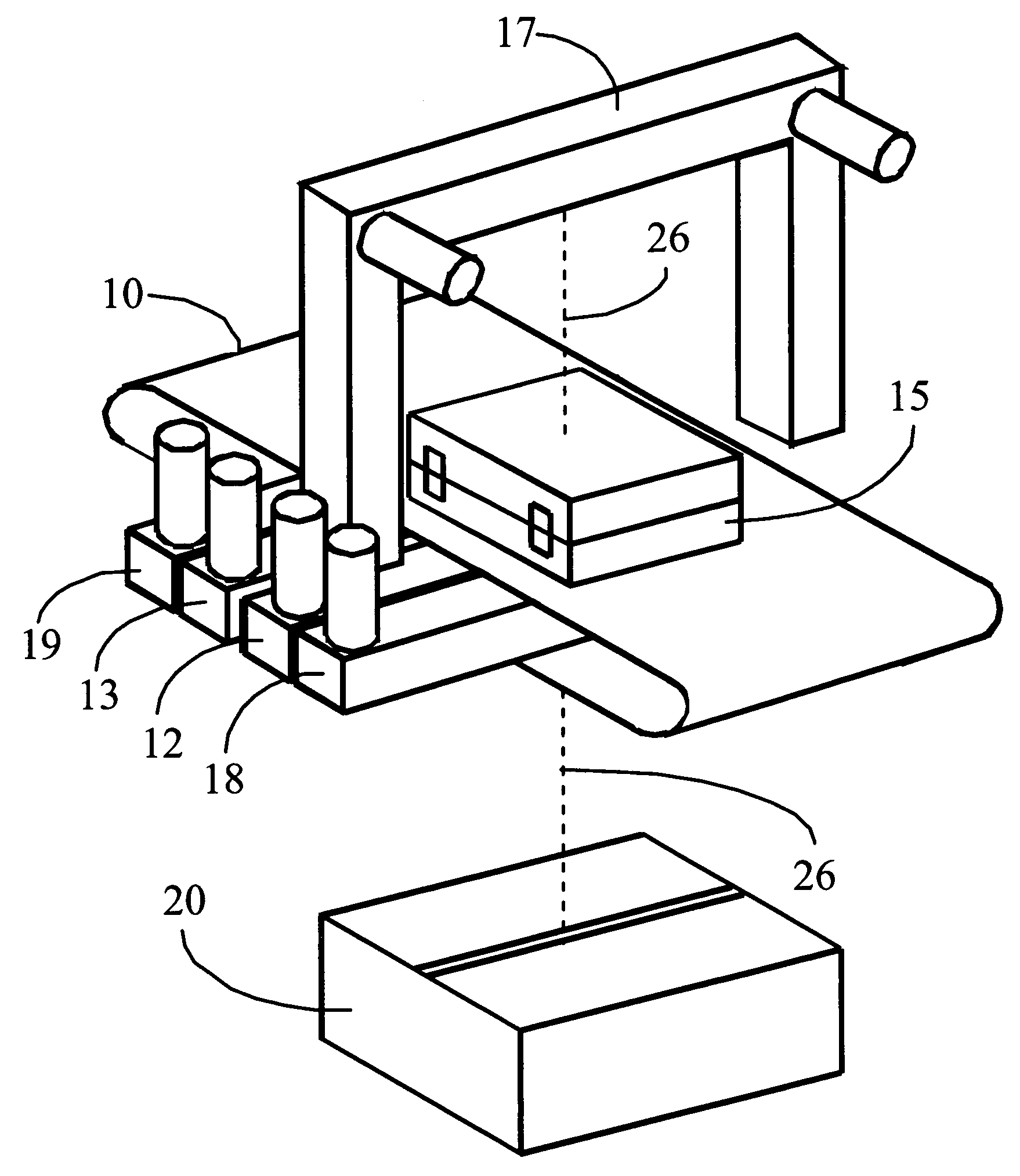
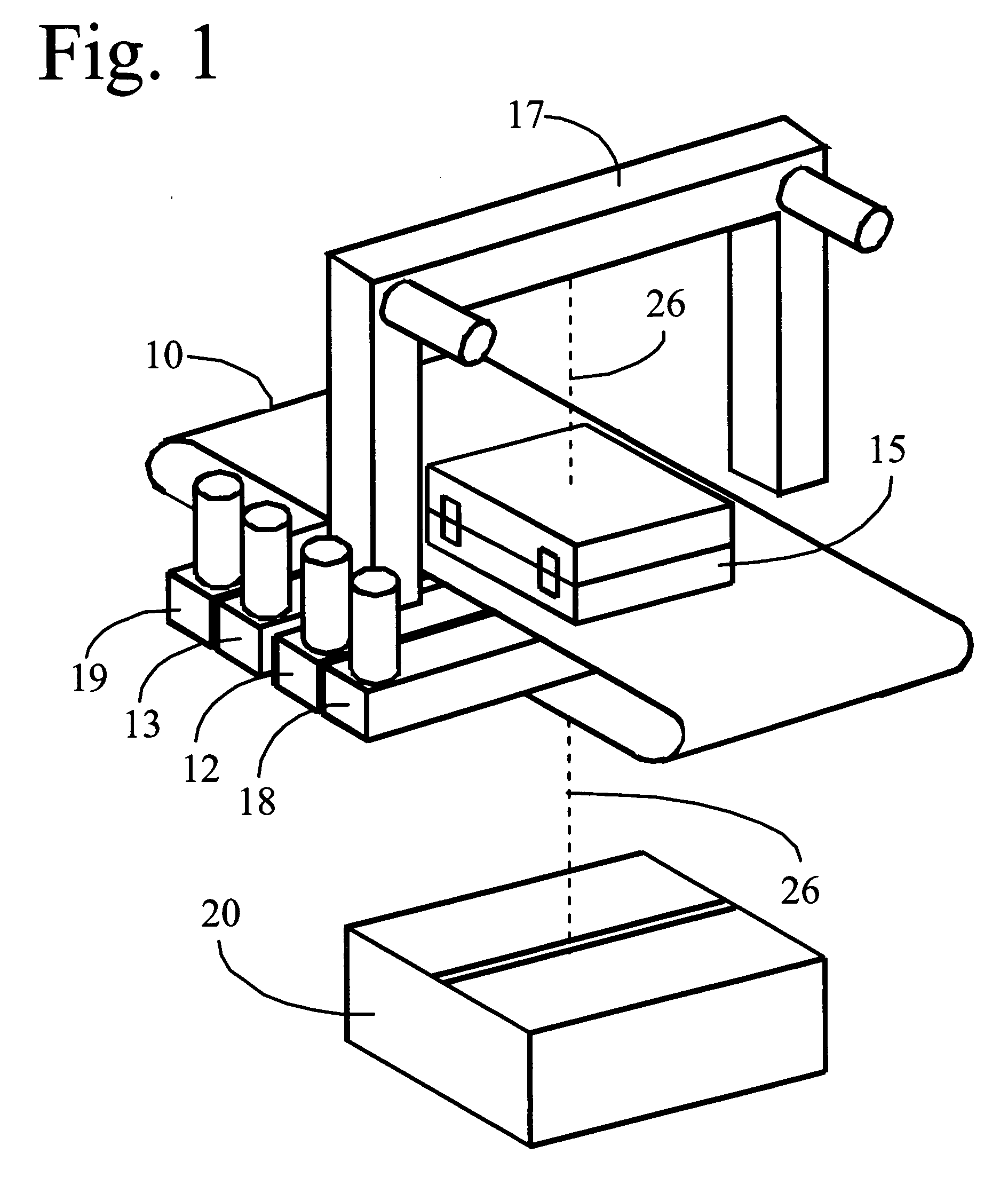
[0031] The invention provides an apparatus and method for X-ray inspection systems that utilize radiation transmitted through and scattered from the object under inspection to detect weapons, narcotics, explosives or other contraband.

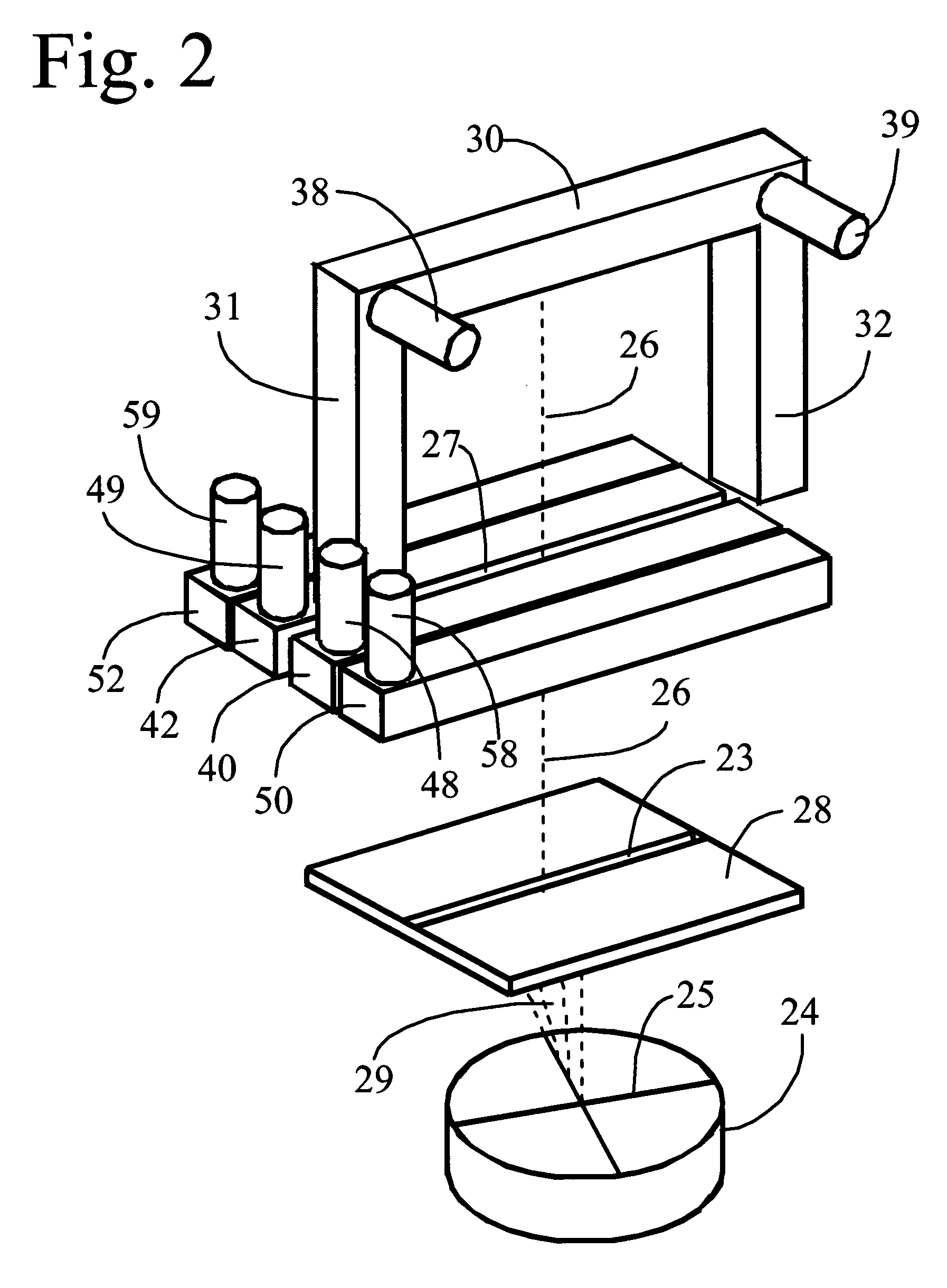
[0032] Specifically, as shown in FIGS. 1 and 2, the invention provides a tomographic scanning X-ray inspection system. The system has conveyor 10 for moving object 15 to be scanned though the system. Object 15 is typically an item of luggage such as a suitcase carried by a traveler. However, any other item such as cargo, freight, boxes, cartons, envelopes, crates, packages, personal articles, and the like, appointed for transport on aircraft, rail, ship, bus or other like public conveyance may also be scanned. The system is also useful for inspecting items to be carried into or delivered to any other public venue such as a courthouse, stadium, auditorium, or like facility. An X-ray generation device 20 generates a pencil beam of X-rays 26. Pencil beam ...


PUM

PropertyMeasurementUnit
angleaaaaaaaaaa
transmissionaaaaaaaaaa
transmission imageaaaaaaaaaa

Abstract

X-ray radiation is transmitted through and scattered from an object under inspection to detect weapons, narcotics, explosives or other contraband. Relatively fast scintillators are employed for faster X-ray detection efficiency and significantly improved image resolution. Detector design is improved by the use of optically adiabatic scintillators. Switching between photon-counting and photon integration modes reduces noise and significantly increases overall image quality.

Description

CROSS-REFERENCE TO RELATED APPLICATION [0001] This application is a Continuation-in-Part of application Ser. No. 10 / 036,953, filed Oct. 19, 2001, entitled “Tomographic Scanning X-Ray Inspection System Using Transmitted And Compton Scattered Radiation”.BACKGROUND OF THE INVENTION [0002] 1. Field of the Invention [0003] The present invention relates to X-ray screening systems for airport luggage and the like; and, more particularly to screening systems that utilize radiation transmitted through and scattered from an object under inspection to detect weapons, narcotics, explosives or other contraband. [0004] 2. Description of the Prior Art [0005] X-ray inspection systems that use transmitted radiation have conventionally been employed to detect the shape of high-Z material (Z refers to atomic number) such as steel. The principal objective of these systems is the detection of weapons, such as guns, knives, bombs and the like. A major problem with X-ray inspection systems is the inabilit...

Claims


Application Information

Patent Timeline
Patent Type & Authority Applications(United States)
IPC IPC(8): G01N23/04G01V5/00
CPCG01N23/046G01V5/0016G01N2223/419G01V5/005G01V5/0025
Inventor MARIO, ARTHUR W.KRAVIS, SCOTT D.
Owner CONTROL SCREENING
Why Eureka
Try Eureka