Radiation imaging system and image processing method

a radiation imaging and image processing technology, applied in the field of radiation, can solve the problems of deteriorating the image quality of phase contrast image, insufficient contrast of x-ray absorption image of living soft tissue or soft materials,

Inactive Publication Date: 2014-09-02
FUJIFILM CORP
View PDF10 Cites 43 Cited by
  • Summary
  • Abstract
  • Description
  • Claims
  • Application Information

AI Technical Summary

Benefits of technology

[0016]An object of the present invention is to provide a radiation imaging system for preventing artifact due to a change in position of a grating between preliminary and main imaging and an image processing method for a radiation imaging system.
[0020]It is preferable that the radiation imaging system further comprises an input section and a controller. The input section inputs an instruction for the preliminary imaging or the main imaging. The controller controls the intensity modulator, the radiation image detector, the phase shift differential image generator, the staircase data generator, and the staircase data adder when the input section inputs the instruction for the preliminary imaging, and allows the storage to store the first added phase shift differential image produced by the staircase data adder.

Problems solved by technology

This causes a problem that sufficient contrast cannot be obtained in the X-ray absorption image of living soft tissue or soft materials.
Distortion, manufacturing error, arrangement error, or the like in the first or second diffraction grating results in offset, whose value corresponds to the distortion, the error, or the like, in the phase shift differential image.
This deteriorates the image quality of the phase contrast image.

Method used


Image

  • Radiation imaging system and image processing method
  • Radiation imaging system and image processing method
  • Radiation imaging system and image processing method

Examples


first embodiment

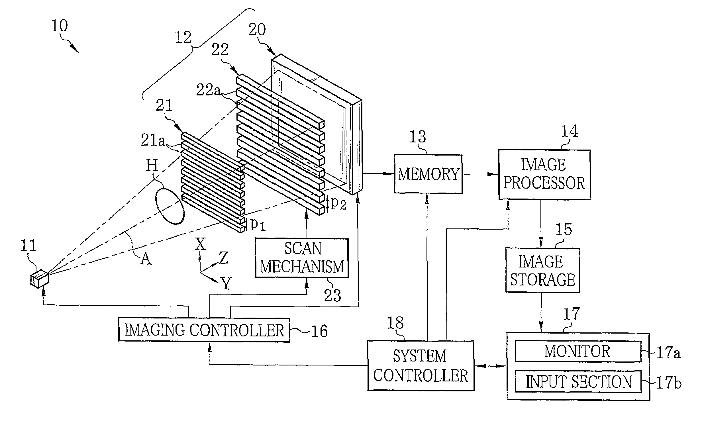
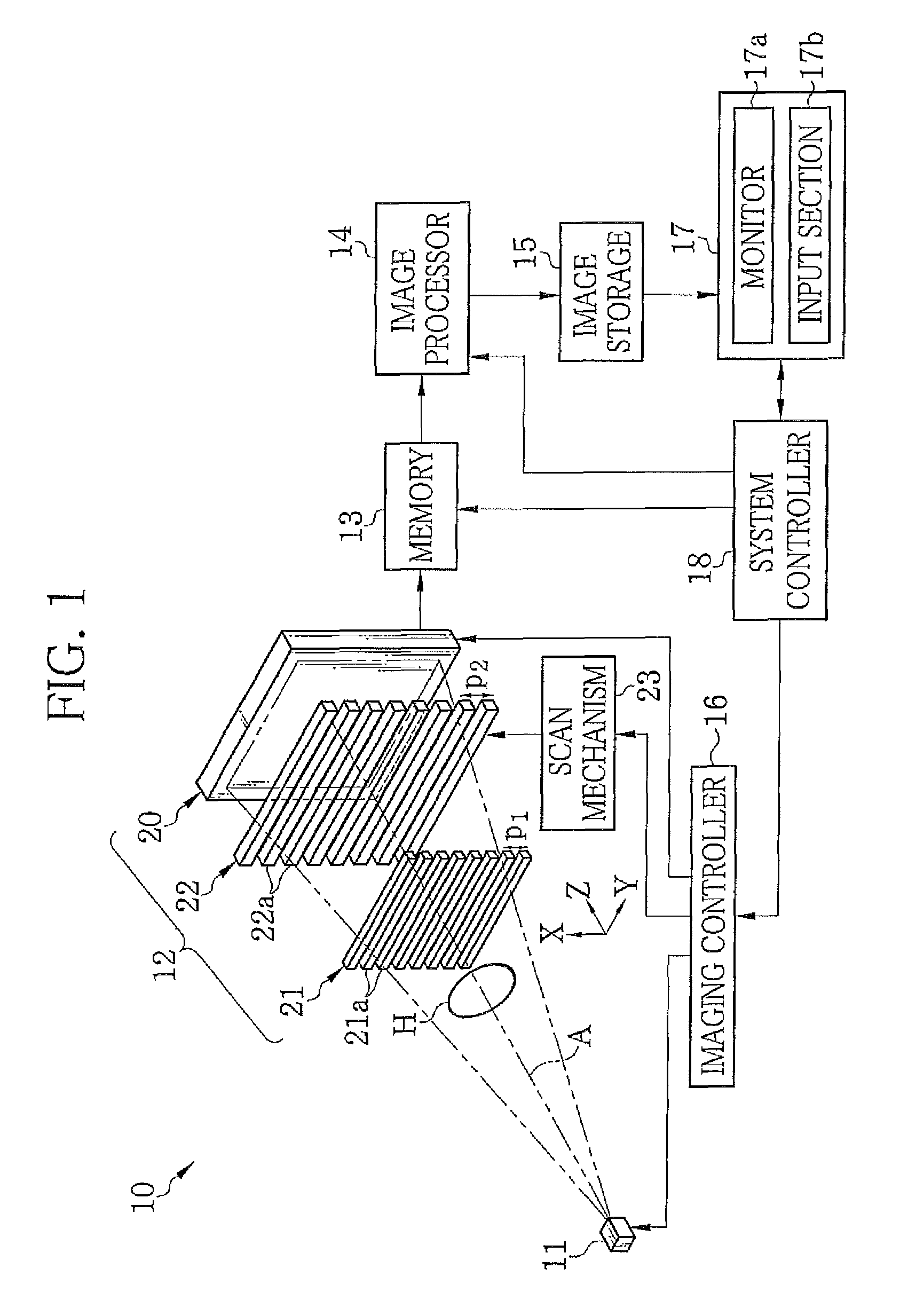
[0056]In FIG. 1, an X-ray imaging system 10 according to a first embodiment of the present invention is provided with an X-ray source 11, an imaging unit 12, a memory 13, an image processor 14, image storage 15, an imaging controller 16, a console 17, and a system controller 18. The X-ray source 11 irradiates a subject H with X-rays. The imaging unit 12 is disposed to face the X-ray source 11, and detects the X-rays, emitted from the X-ray source 11 and passed through the subject H, to produce image data. The memory 13 stores the image data read out from the imaging unit 12. The image processor 14 performs image processing on the pieces of image data, stored in the memory 13, to produce a phase contrast image. The image storage 15 stores the phase contrast image produced by the image processor 14. The imaging controller 16 controls the X-ray source 11 and the imaging unit 12. The console 17 is provided with a monitor 17a and an input section 17b. The system controller 18 controls th...

second embodiment

[0129]In the first embodiment, when the distance between the X-ray source 11 and the FPD 20 is elongated, the image quality of the phase contrast image may be deteriorated by influence of blur in the G1 image due to the focal point size (generally in the order of 0.1 mm to 1 mm) of the X-ray focal point 11a. In a second embodiment of the present invention, as shown in FIG. 15, a multi-slit (source grating) 60 is disposed on the emission side of the X-ray source 11. The X-ray imaging system of the second embodiment is the same as that of the first embodiment except for the multi-slit 60.

[0130]The multi-slit 60 is an absorption-type grating having a configuration similar to those of the first and second absorption-type gratings 21 and 22. The multi-slit 60 has a plurality of X-ray shielding portions 61 extending in the Y direction and arranged periodically in the X direction. The multi-slit 60 partly blocks the X-rays from the X-ray source 11 to reduce the effective focal point size i...

third embodiment

[0132]In the first and second embodiments, the first absorption-type grating 21 is configured to linearly project the X-rays passed through the low X-ray absorption portions 21b. The present invention is not limited to this configuration. The first absorption-type grating 21 can be configured to diffract the X-rays so as to produce the so-called Talbot effect as disclosed in U.S. Pat. No. 7,180,979 corresponding to Japanese Patent No. 4445397. In a third embodiment of the present invention, the first absorption-type grating 21 is a diffraction grating and the distance L2 between the first and second absorption-type gratings 21 and 22 is set to the Talbot length to constitute a Talbot interferometer. In this embodiment, the G1 image (self image) produced by the first grating 21 due to the Talbot effect is formed at the position of the second absorption-type grating 22.

[0133]In this embodiment, the first absorption-type grating 21 may be a phase-type grating (phase-type diffraction gr...


PUM

PropertyMeasurementUnit
tube voltageaaaaaaaaaa
thicknessaaaaaaaaaa
sizeaaaaaaaaaa

Abstract

In each of a first phase shift differential image produced in the absence of a subject in preliminary imaging and a second phase shift differential image produced in the presence of the subject in main imaging, boundaries, at each of which a value changes from π / 2 to −π / 2 or from −π / 2 to π / 2, are determined. First and second staircase data in each of which a value changes by π or −π when crossing each of the boundaries in a predetermined direction is produced. The first and second staircase data is added to the first and second phase shift differential images to produce first and second added phase shift differential image, respectively. The first added phase shift differential image is subtracted from the second added phase shift differential image to produce a corrected phase shift differential image.

Description

CROSS-REFERENCE TO RELATED APPLICATIONS AND PRIORITY CLAIMS[0001]This application is a Continuation of International Application No. PCT / JP2011 / 065572 filed on Jul. 7, 2011, which was published under PCT Article 21(2) in Japanese, which is based upon and claims the benefit of priority from Japanese Patent Applications Nos. 2010-183839, which was filed Aug. 19, 2010, and 2011-020503, which was filed Feb. 2, 2011, the contents of all of which are incorporated herein by reference in their entirety.BACKGROUND OF THE INVENTION[0002]1. Field of the Invention[0003]The present invention relates to a radiation imaging system using radiation to capture an image of a subject and an image processing method for a radiation imaging system, and particularly to a radiation imaging system using a fringe scanning method and an image processing method for a radiation imaging system using a fringe scanning method.[0004]2. Description Related to the Prior Art[0005]Radiation, for example, X-rays, is atte...

Claims


Application Information

Patent Timeline
Patent Type & Authority Patents(United States)
IPC IPC(8): G01N23/04A61B6/00
CPCG01N23/04A61B6/5264A61B6/484A61B6/488A61B6/5235A61B6/4291G01N23/041
Inventor ISHII, HIROYASU
Owner FUJIFILM CORP
Why Eureka
Try Eureka