Construction Technology of Lifting and Installing Large Steel Truss Roof on Both Sides Outside the Span

A technology of large-scale steel truss and construction technology, which is applied in the processing of building materials, construction, building construction, etc., can solve the problems of restricted use, high construction cost, occupation, etc., and achieve the effect of reducing project cost

Active Publication Date: 2019-07-19
浙江中南绿建科技集团有限公司
View PDF8 Cites 0 Cited by
  • Summary
  • Abstract
  • Description
  • Claims
  • Application Information

AI Technical Summary

Problems solved by technology

Each of the above-mentioned assembly constructions has certain advantages, but there are also certain deficiencies. The accumulative slip construction needs to set up multiple slip beams and the slip beams should be distributed in parallel straight lines. It is difficult to adopt the cumulative slip construction technology for space steel trusses; the high-altitude bulk construction technology of building a full hall support frame has defects such as auxiliary measures, high construction costs, and long construction periods, which also affect the cross-implementation of related professions and types of work; segmented hoisting The construction process requires local load-bearing support frames to be erected indoors, and sometimes mobile lifting equipment needs to be arranged indoors, which restricts the use of this process when there are basements or indoor concrete floor strengths that cannot meet the conditions for the use of mobile lifting equipment; Upgrading the construction process also needs to occupy the vertical projection area of ​​the lower part of the space steel truss to be installed. For the space steel trusses with floor structures or spectator stands in the lower part, the assembly site cannot be provided because of the lower ground, which makes the upgrading construction process unable to meet the requirements. construction

Method used


Image

  • Construction Technology of Lifting and Installing Large Steel Truss Roof on Both Sides Outside the Span
  • Construction Technology of Lifting and Installing Large Steel Truss Roof on Both Sides Outside the Span
  • Construction Technology of Lifting and Installing Large Steel Truss Roof on Both Sides Outside the Span

Examples


Embodiment Construction

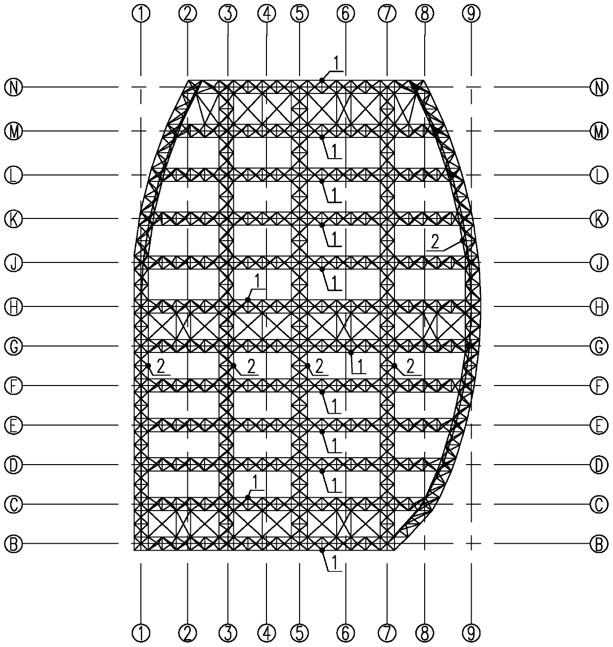
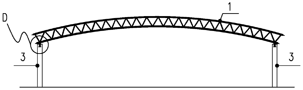
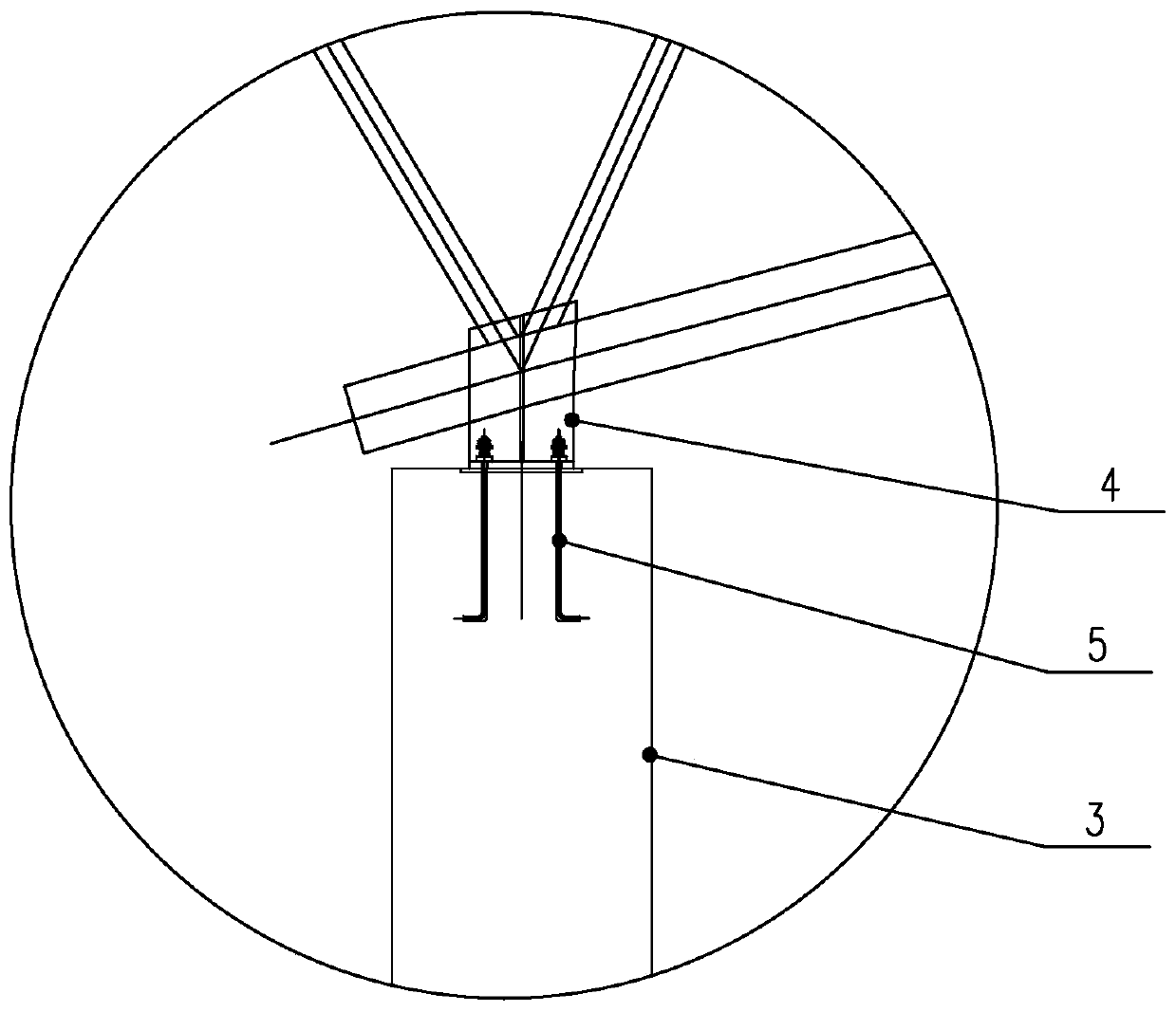
[0050] Such as Figure 1 to Figure 17 As shown, it is the construction technology of the present invention to lift and install a large-scale steel truss roof on both sides of the span. The space steel truss mainly includes a main truss 1 and a secondary truss 2 . The construction process includes the following steps:

[0051] a. Construction preparation

[0052] 1) Determine the construction plane layout: the construction plane layout clearly defines the location of the hoisting machinery walking outside the span, the lifting stations of the hoisting machinery, and the ground assembly area of ​​the steel truss. The walking and lifting stations of the crane outside the span are located on both sides of the longitudinal span of the building, and the ground assembly area of ​​the steel truss is located at both ends of the building or at one end of the building.

[0053] 2) Determine the installation sequence of steel trusses, and determine the sequence of truss ground assembly ...


PUM


Abstract

The invention discloses a construction technology for hoisting a large-size steel truss roof from two outer sides. The construction technology includes the following steps: a, performing constructionpreparation; b, performing primary truss hoisting installation preparation; c, performing primary truss ground assembly; d, performing cycled hoisting on a primary truss from two outer sides in stepsand performing installation; and e, installing a secondary truss according to an installation position of the primary truss. In construction, hoisting devices stand outsides and near two ends of a spatial steel truss to perform hoisting, the hoisting rated capacity demand of the hoisting devices is greatly lowered, the use efficiency of the hoisting devices is improved, and indoor places can be avoided; conflicts of crossed construction between on-site assembly and building of the spatial steel truss and lower other professional workers can be avoided; scaffolds and bearing supports can be avoided; and the construction technology is suitable for assembly and building of the spatial steel structure having a curved or irregular supporting seat, and can reduce the project cost.

Description

technical field [0001] The invention belongs to the technical field of large-span building structures, and in particular relates to a construction technique for hoisting and installing a large-scale steel truss roof on both sides of the span. Background technique [0002] In order to meet the needs of people's life and industrial production, more and more large-span space steel truss structures are used. At the same time, in order to save land, more and more large-span building structures adopt the form of underground structures. [0003] With the emergence of new prefabricated construction technology of building steel structures and large-scale hoisting machinery and equipment, various mature construction techniques have been formed through the assembly and implementation of large-span space steel trusses, such as construction with cumulative slippage, erection of full hall supports The frame is used for high-altitude bulk construction, segmental hoisting construction, lift...

Claims


Application Information

Patent Timeline
Patent Type & Authority Patents(China)
IPC IPC(8): E04G21/14E04G21/18
CPCE04G21/14E04G21/185
Inventor 袁国平吴方亮李昌林杨叶锋赵冠江蒋永扬苏更生
Owner 浙江中南绿建科技集团有限公司
Why Eureka
Try Eureka